Sweeping blade device with adjustable blades

a technology of sweeping blades and adjustable blades, which is applied in the direction of snow cleaning, way cleaning, construction, etc., can solve the problems of premature damage to the blade and/or the entire assembly, unfavorable blade movement, and unfavorable us

Active Publication Date: 2021-01-05
USINAGE PRO24
View PDF104 Cites 2 Cited by
  • Summary
  • Abstract
  • Description
  • Claims
  • Application Information

AI Technical Summary

Benefits of technology

[0015]In one embodiment, the resilient material bushing comprises one or more air gaps for increasing its compressibility, and thus, a movement flexibility of the blade.
[0020]In another aspect there is provided a sweeping blade assembly for attachment to a vehicle for sweeping a ground surface, the sweeping blade assembly comprising: a blade support for receiving blades; a first row of blades comprising a plurality of first-row blades which are attached directly onto the blade support and being separated from each other by a first-row gap; a second blade support comprising a plurality of second-row blades which are attached to the blade support and being distant from the blade support by the first row of blades, and being separated from each other by a second-row gap; wherein each one of the first-row gaps is covered by a corresponding one of the second-row blades, thereby preventing formation of an interstice when a blade undergoes movement.
[0022]In another embodiment, the blades are attached to the blade support using compressible bushings which allow for limited free movement of the blade in an angular manner and / or in a vertical manner.
[0023]In another aspect, there is provided a sweeping blade assembly comprising: a blade support; a plurality of blades removeably attached to the blade support using compressible bushings and having a substantially rectangular shape; wherein adjacent ones of the blades are arranged in distinct planes to allow angular movement of the blades; and wherein each one of the plurality of blades has two sweeping edges to provide reversibility.
[0024]In another aspect there is provided a snow plow blade assembly for sweeping snow, the snow plow blade assembly comprising: a first row of blades comprising a plurality of first-row blades spaced apart by a first-row gap; a second row of blades comprising a plurality of second-row blades spaced apart by a second-row gap; wherein each blade is attached to the blade support by a bushing assembly comprising a resilient material, whereby each blade can undergo limited and independent movement with respect to the blade support; wherein each one of the first-row gaps is covered by a corresponding one of the second-row blades, thereby preventing formation of an interstice when a blade undergoes movement.
[0025]In another aspect, there is provided a snow plow blade assembly for sweeping snow, the sweeping blade assembly comprising: a plurality of blades having a substantially rectangular shape, adjacent ones of the blades being arranged in distinct planes to allow angular movement of the blades; wherein each one of the plurality of blades has two sweeping edges to provide reversibility.

Problems solved by technology

The typical challenge of these vehicles is the presence of uneven surfaces and obstacles on the road especially those of a protruding nature e.g. bumps, which cause uneven wear and premature damage to the blade and / or the entire assembly accompanied by an uneven cleaning of the areas surrounding the protruding obstacle.
While the system described in U.S. Pat. No. 9,121,151 is an improvement over its prior devices, the movement of the blades is still limited and does not allow for an efficient cleaning of the surface surrounding the obstacle.
Furthermore, movement of the blades may result in the creation of interstices which let snow pass therethrough, thereby leaving snow traces inside the plowed area.
Moreover, the blades used in this system cannot be reversed due to their tapered top, which means that once the carbide is worn on the lower edge of the blade, the entire blade would have to be changed.

Method used


Image

  • Sweeping blade device with adjustable blades
  • Sweeping blade device with adjustable blades
  • Sweeping blade device with adjustable blades

Examples


Embodiment Construction

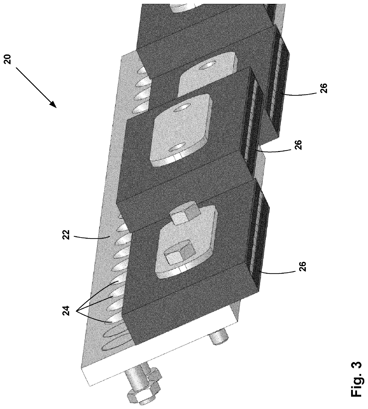
[0045]The embodiments describe a sweeping blade assembly for attachment to a vehicle for sweeping a ground surface. The sweeping blade assembly comprises: a blade support for receiving a plurality of blades, a first row of blades and a second row of blades. Each row of blade comprising a plurality of blades which are separated from each other by a gap. The first row of blades and the second row of blades are provided beside (and parallel to) each other and are positioned so that a given gap in a given row corresponds to (faces) a blade in the other row, and vice versa. In an embodiment, the gap is dimensioned to be smaller in width than the blades whereby a given blade in one row can have a partial overlap of two different blades in the other row. Whereby, the blades can freely move vertically and / or angularly when hitting uneven surfaces, and can be rectangular in shape, and thus, reversible when the carbide on one of the edges is worn out.

[0046]FIG. 3 illustrates an example of a s...


PUM


Abstract

A sweeping blade assembly for attachment to a vehicle for sweeping a ground surface. The sweeping blade assembly comprises: a blade support for receiving a plurality of blades, a first row of blades and a second row of blades. Each row of blade comprising a plurality of blades which are separated from each other by a gap. The first row of blades and the second row of blades are provided beside (and parallel to) each other and positioned so that a given gap in a given row corresponds to a blade in the other row. In an embodiment, the gap is dimensioned to be smaller in width than the blades whereby a given blade in one row can have a partial overlap of two different blades in the other row. Whereby, the blades can freely move vertically and / or angularly when hitting uneven surfaces, and can be rectangular in shape, and thus reversible when the carbide on one of the edges is worn out.

Description

CROSS-REFERENCED TO RELATED APPLICATIONS[0001]This application is a national phase entry of PCT Patent Application Serial No. PCT / CA2017 / 050082, filed Jan. 26, 2017, (now pending) designating the United States of America.BACKGROUND(a) Field[0002]The subject matter disclosed generally relates to sweeping blade devices.(b) Related Prior Art[0003]Snowplowing vehicles are well known in countries that experience significant snowfall and severe cold. Such vehicles include a sweeping blade which travels over the surface of a substrate such as a road, airport, runway, parking lot or the like for removing snow, ice and debris.[0004]The typical challenge of these vehicles is the presence of uneven surfaces and obstacles on the road especially those of a protruding nature e.g. bumps, which cause uneven wear and premature damage to the blade and / or the entire assembly accompanied by an uneven cleaning of the areas surrounding the protruding obstacle.[0005]Attempts have been made to address this...

Claims


Application Information

Patent Timeline
Patent Type & Authority Patents(United States)
IPC IPC(8): E01H5/06
CPCE01H5/062
Inventor MICHEL, HUGOBERGERON, MARCOMICHEL, STEPHAN
Owner USINAGE PRO24
Why Eureka
Try Eureka