
Magnetic measuring apparatus

a technology of magnetic measuring and measuring apparatus, which is applied in the direction of magnetic field measurement using superconductive devices, instruments, therapy, etc., can solve the problems of reducing the mobility of the spine unable to freely bend the cervical region and the lumbar region of an elderly person, and unable to properly measure the biomagnetism of the elderly person

Active Publication Date: 2021-02-16
RICOH KK +1
View PDF33 Cites 1 Cited by
  • Summary
  • Abstract
  • Description
  • Claims
  • Application Information

AI Technical Summary

Benefits of technology

This configuration enhances signal detection rates while maintaining connectivity to cryocooling systems, ensuring stable and accurate biomagnetism measurements by optimizing the fit of the sensor tube to various anatomical shapes without requiring adjustable mechanisms that might increase costs or risk.

Problems solved by technology

However, because the mobility of the spine of an elderly person is reduced due to aging, an elderly person cannot freely bend the cervical region and the lumbar region.
If the cervical region or the lumbar region of a subject is in a natural state, the center of the end face of the sensor tube is positioned away from the cervical region or the lumbar region of the subject and it becomes difficult to properly measure the biomagnetism.
Also, if the cervical region or the lumbar region is bent by force, the magnetic field generated by the movement of muscles becomes a noise source and the biomagnetism is not properly measured.
However, because the shapes of the cervical region and the lumbar region vary greatly depending on the age and the physical constitution of a subject, there are many cases where the curved shape of the sensor tube does not properly fit the cervical region and the lumbar region of a subject.
In such cases, a gap is formed between the subject and the curved end face, a distance between magnetic sensors and the spinal cord becomes large, and it becomes difficult to detect signals.
However, adding a swing mechanism greatly increases the costs of the magnetic measuring apparatus, may reduce the stability, and may increase vibration noise generated during the measurement of biomagnetism.
Also, adding a swing mechanism to the magnetic measuring apparatus makes it impossible to connect the magnetic measuring apparatus to a cryocooling system having a function to recondense vaporized helium into liquid.
As described above, it is extremely difficult to enable a magnetic measuring apparatus to be connected to a cryocooling system while improving the signal detection rate.
Accordingly, this approach may place the subject at risk and is not realistic.

Method used


Image

  • Magnetic measuring apparatus
  • Magnetic measuring apparatus
  • Magnetic measuring apparatus

Examples


example 1

[0050]X-ray photography and biomagnetism measurement of the cervical region were conducted in a manner similar to Comparative Example 1 except that the magnetic measuring apparatus 10 including the incline mount 11 was used instead of the magnetic measuring apparatus 10x that does not include the incline mount 11.

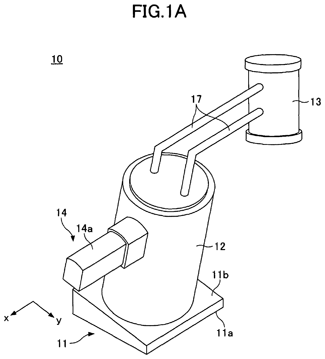
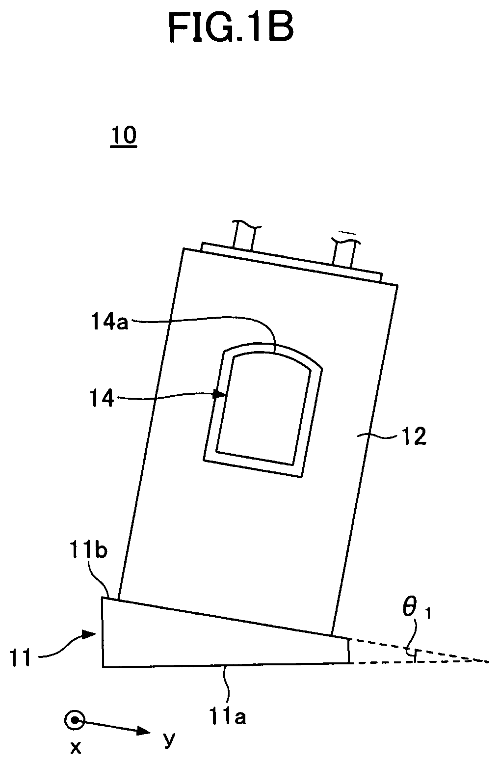
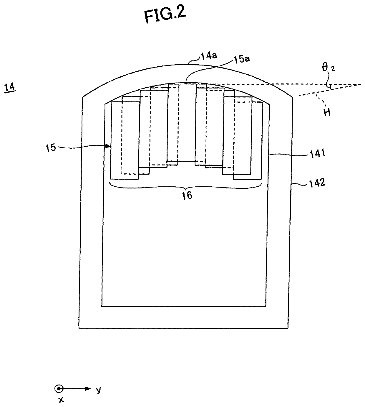
[0051]In Example 1, the inclination gantry 11 with an inclination angle θ1 of 5 degrees was used, and the inclination angle θ2 was set at 5 degrees. Because the upper surface of the bed 21 is horizontal (or parallel to the mount surface 11a), the inclination angle θ2 becomes equal to an angle (which is hereafter referred to as an angle θ3) formed between an examination region of the subject 500 and the sensor surfaces 15a of the magnetic sensors 15.

[0052]The average distance L was 107.1 mm, the largest distance L was 151 mm, and the smallest distance L was 93 mm. Thus, the distance L was significantly reduced compared with Comparative Example 1. Here, the significant reduct...

example 2

[0054]X-ray photography and biomagnetism measurement of the cervical region were conducted in a manner similar to Example 1 except that the inclination angle θ1 was set at 10 degrees and the inclination angle θ2 was set at 10 degrees.

[0055]The average distance L was 103.1 mm, the largest distance L was 121 mm, and the smallest distance L was 87 mm. Thus, the distance L was further reduced compared with Example 1.

[0056]In the measurement at the cervical region using the magnetic measuring apparatus 10, weak propagation signals were detected in 25 subjects out of 27 subjects, and the signal detection rate was 92.6%. Thus, the signal detection rate exceeded 90% and significantly improved compared with Comparative Example 1.

example 3

[0057]X-ray photography and biomagnetism measurement of the cervical region were conducted in a manner similar to Example 1 except that the inclination angle θ1 was set at 15 degrees and the inclination angle θ2 was set at 15 degrees.

[0058]The average distance L was 101.1 mm, the largest distance L was 120 mm, and the smallest distance L was 87 mm. Thus, the distance L measured in Example 3 did not differ greatly from that measured in Example 2.

[0059]In the measurement at the cervical region using the magnetic measuring apparatus 10, weak propagation signals were detected in 25 subjects out of 27 subjects, and the signal detection rate was 92.6%. Thus, the signal detection rate exceeded 90% and significantly improved compared with Comparative Example 1.


PUM


Abstract

A magnetic measuring apparatus includes an inclination gantry including a mount surface and an inclined surface that is inclined with respect to the mount surface, a cryostat disposed on the inclined surface, a cryocooling system connected to the cryostat, a sensor tube connected to the cryostat and including a curved surface that does not curve in a predetermined direction and curves in a direction orthogonal to the predetermined direction such that a center of the curved surface protrudes with respect to side edges of the curved surface, and a magnetic sensor that measures biomagnetism and is housed in the sensor tube such that a sensor surface of the magnetic sensor faces the curved surface. The sensor surface is inclined with respect to the mount surface in a direction that is the same as a direction in which the inclined surface is inclined.

Description

CROSS-REFERENCE TO RELATED APPLICATIONS[0001]The present application is a continuation application filed under 35 U.S.C. 111(a) claiming benefit under 35 U.S.C. 120 and 365(c) of PCT International Application No. PCT / JP2017 / 005824, filed on Feb. 17, 2017, which is based on and claims the benefit of priority of Japanese Patent Application No. 2016-041406 filed on Mar. 3, 2016, the entire contents of which are incorporated herein by reference.BACKGROUND OF THE INVENTION1. Field of the Invention[0002]An aspect of this disclosure relates to a magnetic measuring apparatus.2. Description of the Related Art[0003]There is a known magnetic measuring apparatus including a sensor array that is composed of multiple superconducting magnetic sensors arranged in rows and columns and is disposed on the inner surface of an end portion of a sensor tube (see, for example, Japanese Patent No. 4397276).[0004]An end face of the sensor tube of the magnetic measuring apparatus is brought into contact with ...

Claims


Application Information

Patent Timeline
Patent Type & Authority Patents(United States)
IPC IPC(8): G01R33/035A61B5/05A61B5/04A61B5/00A61B6/04A61B6/00G01R33/00A61N1/04
CPCA61B5/04005A61B5/0035A61B5/05A61B5/4041A61B5/704A61B6/045A61B6/5247G01R33/0082G01R33/035A61B2562/0223A61B2562/164A61N1/0456A61B5/242
Inventor YAMAGA, TAKUMIDEGUCHI, HIROSHIYAMAGUCHI, KOJIISHIBE, TAKAFUMIMATSUMOTO, SHUNICHIKAWABATA, SHIGENORIUSHIO, SHUTA
Owner RICOH KK
Learn More