Displays

a colour display and projection technology, applied in the field of projection colour display systems, can solve the problems of so-called ‘colour break-up’, the risk that some symbols may be much more difficult to distinguish than others, and the difficulty of identifying symbols,

Active Publication Date: 2021-03-23
BAE SYSTEMS PLC
View PDF18 Cites 0 Cited by
  • Summary
  • Abstract
  • Description
  • Claims
  • Application Information

AI Technical Summary

Benefits of technology

[0016]Preferably, the first component image is displayed using the first component colour simultaneously with the second component colour in the absence of the third component colour thereby to display the first component image as another resultant colour. It has been found the human eye is relatively responsive to Red light and that sufficient visibility of purely red symbols is achievable. However, in preferred embodiments, the first component image may be displayed using a resultant colour enabling better visibility to the user.
[0028]Thus, in summary, the component images of the display may be displayed using at least three (e.g. optionally five, or more) different colours (e.g. two or more different resultant colours, and one component colour which is different to the two or more resultant colours) of efficiently controllable luminance levels using just three component colours. An additional advantage of the methodology is that because the resultant colours are each generated using two component colours simultaneously, not sequentially, this means that the resultant colours do not suffer from colour break-up problem described above. Thus in addition to being able to control colour luminance efficiently as desired to permit good user-perception, the invention may at least to some extent mitigate the effects of colour break-up at the same time.

Problems solved by technology

However, the applicant has realised that the use of full-colour symbology, as opposed to simpler monochrome symbology, in these circumstances can introduce a number of problems.
Most notable amongst these problems is that current technologies require the use of relatively few component colours (e.g. Red, Green, Blue) to draw symbology which may be required in a large number of different colours (e.g. different symbols assigned different colours for intelligibility).
Bearing in mind that the human eye responds to different colours differently, being most responsive to the green part of the visible spectrum, and less so to other spectral regions, this introduces the risk that some symbols may be much more difficult to distinguish than others due to their particular colour.
This may be particularly problematic in see-through HMDs because the colour symbols are to be viewed against the background of the external environment seen by the user (e.g. bright clouds, in the case of a pilot).
If the displayed image is created by a device employing field-sequential colour display methods then the problem of so-called ‘colour break-up’ will arise.

Method used


Image

  • Displays
  • Displays
  • Displays

Examples


Embodiment Construction

[0053]In the drawings, like items are assigned like reference symbols.

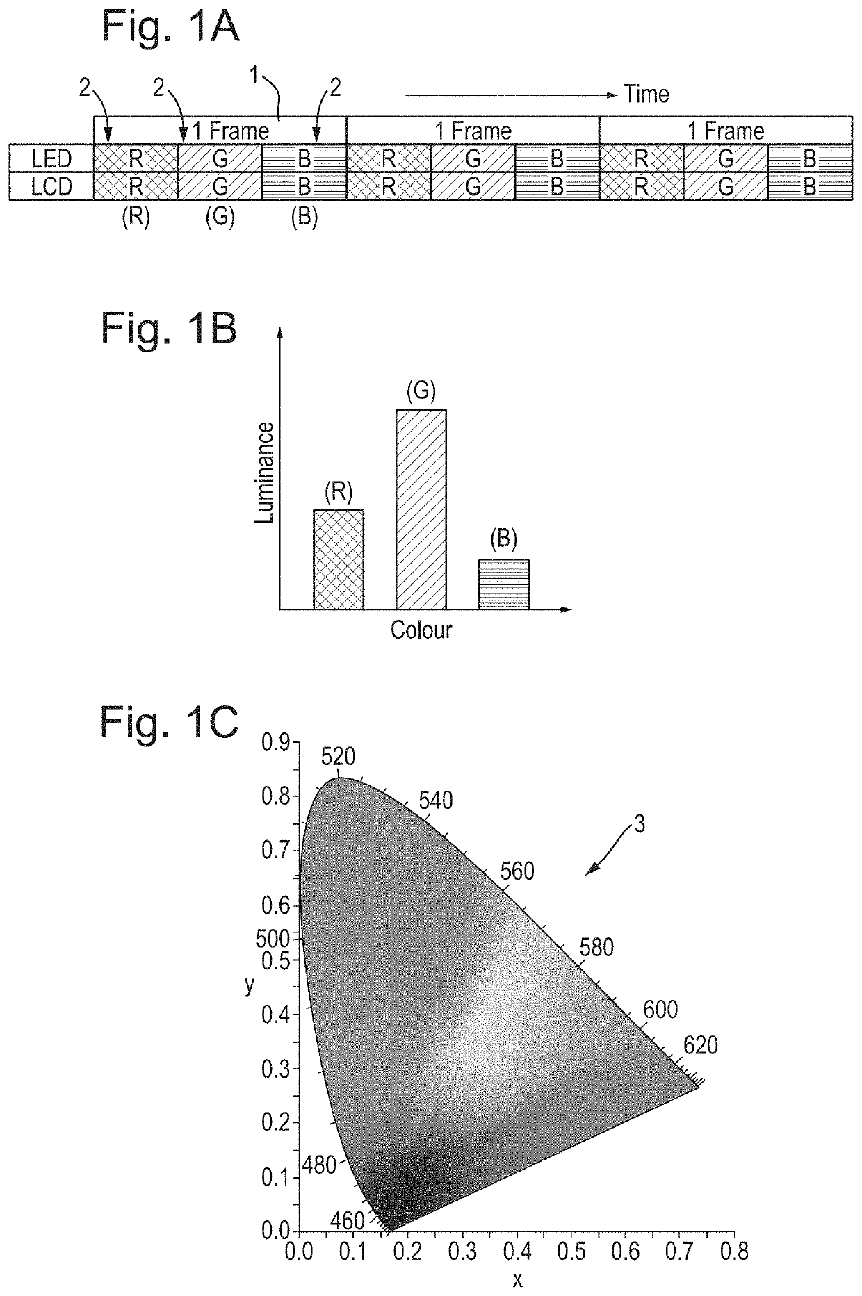
[0054]FIG. 1A schematically illustrates a conventional field-sequential colour projection display timing control arrangement for use in displaying colour video by projection. A combination of three component images (2) each representing a respective one of three different component colours (red=R; green=G; blue=B) of a video image frame are displayed sequentially each within a respective sub-frame portion of the same one image frame display period (1). By sequentially displaying the red, green and blue image content at a sufficiently high frequency, the human eye integrates the colour content together to form a colour image within each frame period.

[0055]In particular, a red LED light source is arranged to illuminate and LCD projection display panel during a 1st sub-frame portion of a frame period within which the LCD display panel is controlled to draw or present the red component image of the video image frame. ...


PUM


Abstract

Apparatus and method for field-sequential colour display of a colour image comprising a combination of three component images each representing a respective one of three different component colours of the image. Sequentially, the following steps are performed within a common display frame period. A first component image is displayed using the first component colour. Separately, the second component image is displayed using the second component colour without either of the first component colour and the third component colour. This displays the second component image as a second colour. Separately, the third component image is displayed using the third component colour simultaneously with the second component colour without the first component colour thereby to display the third component image as a resultant colour.

Description

FIELD OF THE INVENTION[0001]The invention relates to colour display systems and methods. In particular, though not exclusively, the invention relates to projection colour display systems and methods, preferably, though not exclusively, for use in Helmet Mounted Displays (HMD).BACKGROUND[0002]Helmet-Mounted Displays (HMD) aim to provide an improved piloting capability and are adapted for use with aircraft pilots and optionally ‘pilots’ of other vehicles. An HMD is typically adapted to display data e.g. flight parameters in the pilot's field of view to avoid having to consult Head Down Displays at critical moments. The displayed data often takes the form of symbology which is projected for display such that symbols representing outside-world entities move in line with the pilot's head movements. This is discussed in more detail below.[0003]Recent developments in helmet-mounted displays provide full-colour dynamic data, such as flight data, projected directly into a user's line of sigh...

Claims


Application Information

Patent Timeline
Patent Type & Authority Patents(United States)
IPC IPC(8): G09G5/02G09G3/34
CPCG09G5/026G09G3/3413G09G2320/0242G09G2320/0261G09G2354/00G09G2380/12G09G3/36H04N9/3111G09G2310/0235G02B27/017H04N9/3155H04N9/3164G02B2027/0112
Inventor HOBSON, ROSS RENWICK
Owner BAE SYSTEMS PLC
Why Eureka
Try Eureka