Check patentability & draft patents in minutes with Patsnap Eureka AI!

Load support structure for chair, load support body for chair, and chair

a technology for supporting structures and chairs, which is applied in the direction of chairs, stools, domestic applications, etc., can solve the problems of inability to stably support the body of the seated person, the seat frame is not sufficiently deformed, and the seated person feels pain or discomfort, etc., to suppress excessive displacement and suppress excessive displacement

Active Publication Date: 2021-06-01
OKAMURA CORP
View PDF27 Cites 0 Cited by
  • Summary
  • Abstract
  • Description
  • Claims
  • Application Information

AI Technical Summary

Benefits of technology

The present invention relates to a load support structure for a chair and a chair with this structure. The technical effect of this invention is that it can allow the support section or the annular body to have elastic deformation while suppressing excessive displacement. This provides better comfort and stability for the chair occupant while also improving the overall performance of the chair.

Problems solved by technology

Therefore, only the tensile material stretched on the frame member is displaced in the surface perpendicular direction, and the frame member itself such as the clamping frame or the seat frame does not sufficiently deform against the load of a seated person and is not able to stably support the body of the seated person.
In addition, when the load of the seated person acts on a position eccentric from the center of the tensile material, the frame member may come into contact with the body of the seated person and make the seated person feel pain or discomfort.

Method used


Image

  • Load support structure for chair, load support body for chair, and chair
  • Load support structure for chair, load support body for chair, and chair
  • Load support structure for chair, load support body for chair, and chair

Examples


first embodiment

[0063]Hereinafter, a chair according to a first embodiment of the present invention will be described with reference to the drawings.

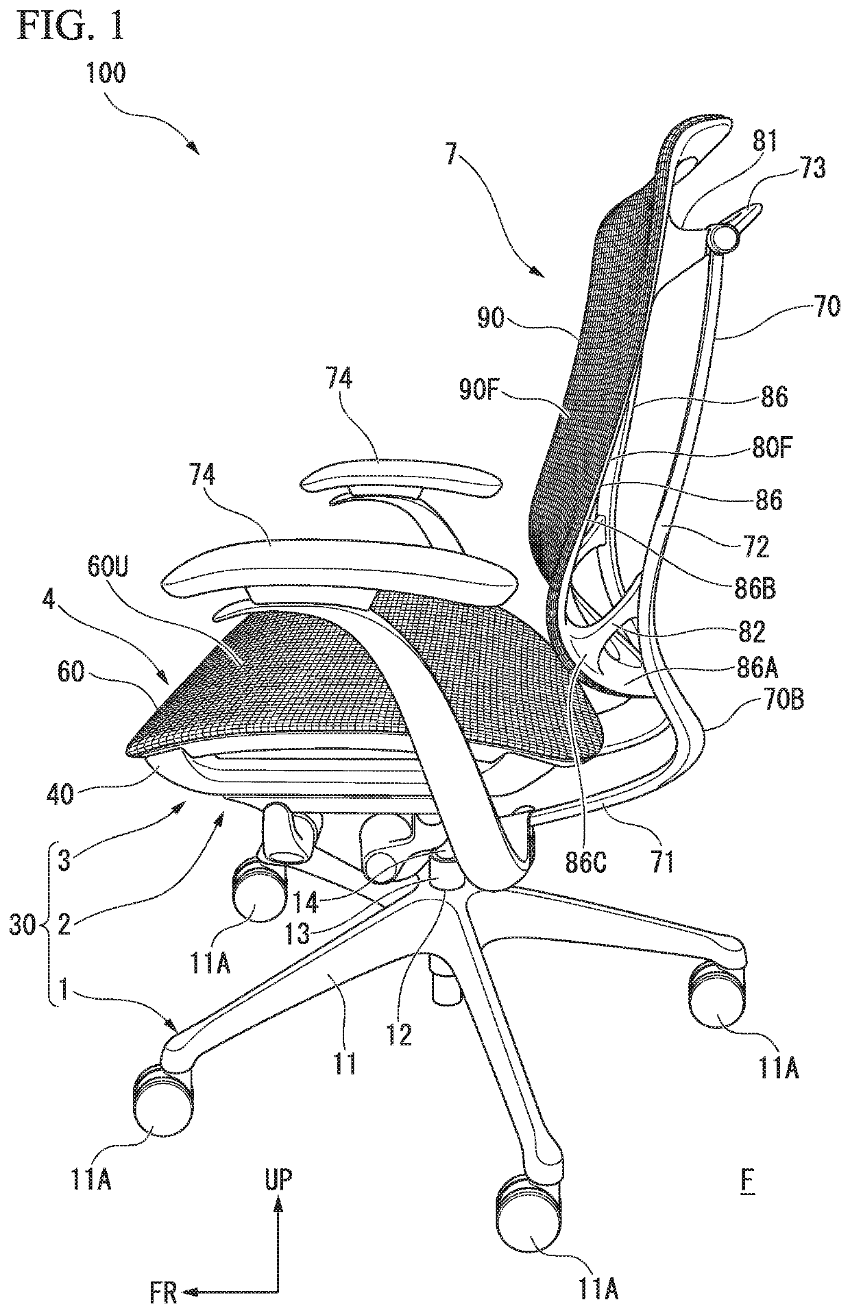
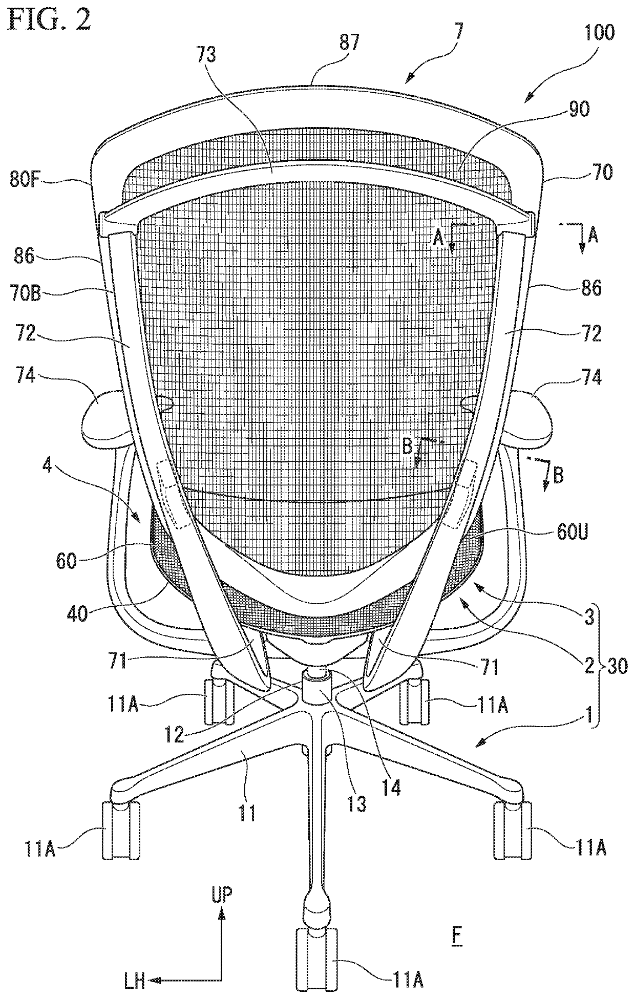
[0064]FIG. 1 is a perspective view of a chair according to the first embodiment of the present invention as viewed from a lateral side. FIG. 2 is a perspective view of the chair according to the first embodiment of the present invention as viewed from behind (backrest side).

[0065]As shown in FIGS. 1 and 2, a chair 100 has a leg section 1 installed on a floor surface F, a box-like support base 2 (not shown) installed on an upper part of the leg section 1, a seat receiving member 3 attached to an upper part of the support base 2, a seat body (a load support structure of the chair) 4 that is slidably supported by the seat receiving member 3 and on which a seated person sits, and a backrest (a load support structure for a chair) 7 extending from the support base 2 to support the back of the seated person seated on the seat body 4.

[0066]In the following des...

second embodiment

[0138]Hereinafter, a chair according to the second embodiment of the present invention will be described with reference to the drawings.

[0139]FIG. 8 is a perspective view of a chair according to the second embodiment of the present invention as viewed from a lateral side. FIG. 9 is a perspective view of the chair according to the second embodiment of the present invention as viewed from behind (the backrest side).

[0140]As shown in FIGS. 8 and 9, a chair 200 has a leg section 201 installed on a floor surface F, a box-like support base 202 (not shown) installed on an upper part of the leg section 201, a seat receiving member 203 attached to an upper part of the support base 202, a seat body (a load support body for a chair) 204 that is slidably supported by the seat receiving member 203 and on which a seated person sits, and a backrest 207 extending from the support base 202 to support the back of the seated person seated on the seat body 204.

[0141]In the following description, for co...


PUM


Abstract

A load support structure for a chair includes a tensile material on which a load support surface configured to receive a load of a seated person is formed, a pair of support sections (51) to which the tensile material is attached, and which is elastically deformable in response to a force acting from the tensile material, a first reinforcing section (41) which is disposed to be spaced apart from the pair of support sections (51) in a surface perpendicular direction perpendicular to the load support surface, is located on a side opposite to the load support surface, and extends along an extending direction of the support section, and a connecting body which connects each of both end portion sides of the support section (51) with a corresponding end portion side of both end portion sides of the first reinforcing section (41), in which the support sections (51) are disposed outside the first reinforcing section (41) in a view of the surface perpendicular direction from the load support surface side.

Description

TECHNICAL FIELD[0001]The present invention relates to a load support structure for a chair, a load support body for a chair, and a chair.[0002]Priority is claimed on Japanese Patent Application No. 2016-116273, filed Jun. 10, 2016, and Japanese Patent Application No. 2016-116274, filed Jun. 10, 2016, the contents of which are incorporated herein by reference.BACKGROUND ART[0003]In the related art, a load support structure for a chair and a load support body for a chair, such as a backrest member or a seat member, including a frame member as a strength member and a tensile material having an elastic resistance (repulsive force) against a load from a surface perpendicular direction are generally known.[0004]For example, as described in Patent Document 1, a chair in which a frame-like seat frame is fixed to a frame-like clamping frame, and an end portion of a net member is caught in a fixing portion between the clamping frame and the seat frame is known. In the fixing portion between t...

Claims


Application Information

Patent Timeline
Patent Type & Authority Patents(United States)
IPC IPC(8): A47C7/00A47C7/28A47C31/02A47C7/40A47C7/32
CPCA47C7/282A47C7/004A47C7/32A47C7/40A47C31/02
Inventor MASUNAGA, HIROSHIIZAWA, SYOUICHI
Owner OKAMURA CORP
Features
  • R&D
  • Intellectual Property
  • Life Sciences
  • Materials
  • Tech Scout
  • Unparalleled Data Quality
  • Higher Quality Content
  • 60% Fewer Hallucinations
Learn More