
Liquid viscoelastic damper

A viscoelastic and damper technology, applied in the field of structural protection, can solve the problems of limited energy dissipation capacity, poor durability and stability, load frequency, and small output, and achieve the effects of avoiding repeated vibration, easy use, and suppressing excessive displacement.

Inactive Publication Date: 2015-06-10
GUIZHOU TRANSPORTATION PLANNING SURVEY & DESIGN ACADEME
View PDF7 Cites 8 Cited by
  • Summary
  • Abstract
  • Description
  • Claims
  • Application Information

AI Technical Summary

Problems solved by technology

However, the solid viscoelastic damper is a device with a laminated structure of metal plates and rubber (or other solid materials with viscous properties), which has small output, limited energy dissipation capacity, poor durability and stability, and limited Many disadvantages such as ambient temperature and load frequency lead to poor applicability

Method used


Image

  • Liquid viscoelastic damper
  • Liquid viscoelastic damper

Examples


Embodiment 1

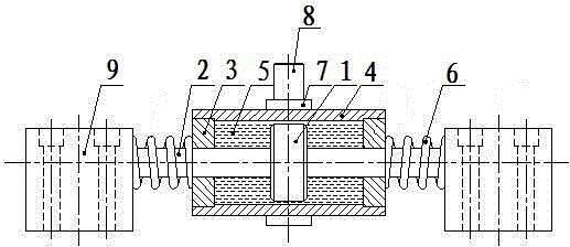
[0013] Embodiment 1 of the present invention: The structure diagram of a liquid viscoelastic damper of the present invention is as figure 1 As shown, the liquid viscoelastic damper includes a damping mechanism composed of a commercially available piston 1, a piston rod 2, an end cover 3, a cylinder 4, and a liquid damping medium 5. The elastic element 6 can be sleeved on both ends of the piston rod 2 to form an elastic mechanism to provide rigid support for the movement of the piston rod 2. Among them, the elastic element 6 can be a cylindrical helical compression spring, a disc spring, or a combination of various existing commercially available springs. The collar 7 can be connected to the cylinder 4, the pin 8 is connected to the collar 7, and then two fixed blocks 9 are respectively installed on the outer sides of the two ends of the piston rod 2 to form a connecting mechanism. Connect one end of the elastic element 6 to the end cap 3, connect the other end of the elastic e...

Embodiment 2

[0015] Embodiment 2 of the present invention: The structure diagram of another liquid viscoelastic damper of the present invention is as follows figure 2 As shown, the liquid viscoelastic damper includes a damping mechanism composed of a commercially available piston 1, a piston rod 2, an end cover 3, a cylinder 4, and a liquid damping medium 5. Two elastic elements 6 can be installed, and the elastic piston 10 is connected to one end of the piston rod 2 to form an elastic mechanism, which provides rigid support for the movement of the piston rod 2. Among them, the elastic element 6 can be a cylindrical helical compression spring, a disc spring, or a combination of various existing commercially available springs. The earring 11 is connected to the other end of the piston rod 2, the outer cylinder 12 is placed outside the elastic mechanism and its inner diameter is made larger than the cylinder 4, and the connecting earring 13 is connected to the outer cylinder 12 to form a con...


PUM


Abstract

The invention discloses a liquid viscoelastic damper. The liquid viscoelastic damper comprises a damping mechanism consisting of a piston, a piston rod, an end cover, a cylinder and a liquid damping medium, wherein the damping mechanism is connected with an elastic mechanism capable of providing rigid support to the movement of the piston rod; and a connecting mechanism connected with an external building structure is arranged on the elastic mechanism. The liquid viscoelastic damper provides the rigidity support through the elastic force generated by compressing and stretching the elastic mechanism to prevent repeated vibration under the condition of low load, adds a limiting function to restrain excessive displacement under static load, and has an automatic reset function. Secondly, the damping mechanism and the elastic mechanism are in a parallel relationship, and are independent from each other, so that the structure damping calculation can be performed through direct addition, and the use is convenient. The liquid viscoelastic damper retains the damping energy consumption function, overcomes multiple defects of a solid viscoelastic damper, is suitable for being promoted in such engineering as large-span bridges and high-rise buildings, and in particular, is suitable for building engineering with severer external environmental condition.

Description

technical field [0001] The invention relates to a structural energy consumption and vibration reduction device, in particular to a liquid viscoelastic damper, which belongs to the technical field of structural protection. Background technique [0002] With the rapid development of the economy, various large bridge buildings emerge in endlessly. Among them, the viscous damper is widely accepted for its excellent damping performance. Viscous dampers are generally composed of pistons, piston rods, cylinders, end covers, damping media, sealing systems, etc. The damping media is viscous liquids, and its energy consumption mechanism is: when the building vibrates, The viscous damper moves accordingly, and the moving piston forces the damping medium inside the cylinder to quickly pass through the preset flow channel. During this process, part of the input energy is converted into heat energy and dissipated, thereby achieving the purpose of reducing structural vibration . It can ...

Claims


Application Information

Patent Timeline
Patent Type & Authority Applications(China)
IPC IPC(8): E04B1/98E01D19/00
Inventor 杜镔刘建军龙万学唐璐宁响亮刘军杨鸿波万麟邓晓红韦定超饶毅刚余洋李银斌陈冠桦唐志
Owner GUIZHOU TRANSPORTATION PLANNING SURVEY & DESIGN ACADEME
Learn More