Check patentability & draft patents in minutes with Patsnap Eureka AI!

Process for producing hot-rolled steel strip and apparatus therefor

a production method and technology applied in metal rolling arrangements, manufacturing tools, shaping tools, etc., can solve problems substantially similar to those described, and achieve the effect of reliably achieving stable running of hot rolled strips, effectively suppressing excessive displacement, and preventing head folding defects

Inactive Publication Date: 2006-01-19
JFE STEEL CORP
View PDF7 Cites 7 Cited by
  • Summary
  • Abstract
  • Description
  • Claims
  • Application Information

AI Technical Summary

Benefits of technology

[0017] The present invention has been made to overcome the above-described problems of the conventional techniques. An object of the present invention is to effectively suppress excessive displacement (for example, jumping or waving) of a hot rolled strip, which runs on a hot runout table, above a pass line by squirting fluid and to reliably prevent a head folding defect, a tail folding defect, and a strip folding defect of the hot rolled strip resulting from the displacement. Another object is to properly prevent a portion of the strip from being displaced above the pass line by the fluid squirting. A further object is to provide a production method and a production system for a hot rolled strip that can reliably achieve stable running of a hot rolled strip on a hot runout able.
[0018] In view of the above-described problems of the conventional methods, the present inventors examined a method for effectively suppressing excessive displacement of a hot rolled strip, which runs on a hot runout table, above a pass line by squirting fluid, and as a result, found the following: (a) In order to achieve stable running of a hot rolled strip on a hot runout table by squirting fluid, it is essential to squirt a beam-shaped fluid jet so as to completely pass over the hot rolled strip without touching a surface of the hot rolled strip normally running on the pass line. This can effectively suppress excessive displacement (for example, jumping or waving) of the hot rolled strip above the pass line, and can properly prevent a portion of the strip from being displaced above the pass line by the squirting of fluid itself. (b) In order to particularly effectively suppress excessive displacement (for example, jumping or waving) of the strip above the pass line, it is necessary to optimize the height of the beam-shaped fluid jet passing over the strip from the pass line in the above (a).
[0022] According to this production method of the present invention, it is possible to effectively suppress excessive displacement (jumping or waving) of a hot rolled strip, which runs on the hot runout table, above the pass line by squirting fluid, and to reliably prevent a head folding defect, a tail folding defect, and a strip folding defect resulting from the displacement. Since the fluid jet completely passes over the hot rolled strip that is normally running without touching the hot rolled strip, displacement of a strip portion above the pass line due to the squirting of fluid can be properly prevented. Consequently, stable running of the hot rolled strip on the hot runout table can be reliably achieved.
[0030] When the fluid jet is squirted in the direction in the above (1), it is preferable that a velocity component in the pass-line longitudinal direction of the fluid jet that is passing above the hot rolled strip be higher than the running velocity of the hot rolled strip. It is particularly preferable that a velocity component in the pass-line longitudinal direction of the fluid jet that is passing above the head end of the hot rolled strip be higher than the running velocity of the hot rolled strip, and that a velocity component in the pass-line longitudinal direction of the fluid jet that is passing above the tail end of the hot rolled strip be lower than the running velocity of the hot rolled strip. These conditions allow the fluid jet to properly act on a strip portion displaced above the pass line.

Problems solved by technology

However, according to the examinations, the present inventors found that the above conventional methods have the following problems: (A) In the conventional methods disclosed in Documents 2, 4, and 5, fluid, such as water, is directly sprayed in an obliquely upward direction onto the surface of a hot rolled strip that is running on a pass line of a hot runout table.
However, when the fluid is directly sprayed onto the surface of the strip on the pass line in an obliquely upward direction, as in these conventional methods, since the fluid has a vertical velocity component, it applies a vertical impact force to the hot rolled strip that is normally running on the pass line of the hot runout table.
After further investigations, however, it was found that problems substantially similar to those in the above (A) arose in these conventional methods.
Since the fluid landing on the strip surface, of course, applies a vertical impact force on the hot rolled strip, problems substantially similar to those described in the above (A) occur.
However, it was found that the above-described problems also arose in the method in Document 3 in which the fluid is not directly sprayed onto the strip surface.
Therefore, Document 1 does not disclose a technical idea in which a beam-shaped fluid jet is squirted so as to completely pass over a hot rolled strip.
However, FIG. 1 of Document 3 shows the water sprayed in a cone-spray form, and does not disclose the technical idea in which a beam-shaped fluid jet is squirted so as to completely pass over the hot rolled strip.

Method used


Image

  • Process for producing hot-rolled steel strip and apparatus therefor
  • Process for producing hot-rolled steel strip and apparatus therefor
  • Process for producing hot-rolled steel strip and apparatus therefor

Examples


Embodiment Construction

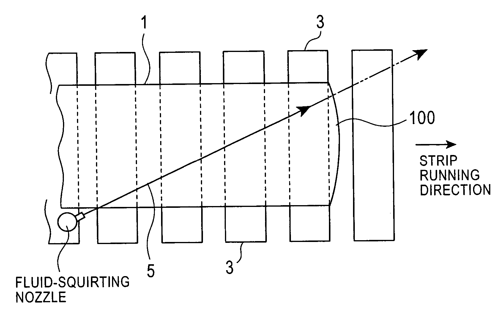
[0080] The present invention relates to a hot-rolled-strip production method in which a hot rolled strip obtained by rolling with a hot rolling mill is conveyed by a hot runout table and is then coiled with a coiler. The method is characterized in a manner in which a fluid jet is squirted in order to correct (suppress, eliminate) the displacement of the hot rolled strip running on the hot runout table above a pass line (for example, jumping or waving at a head or tail end of the strip, the same applies hereinafter).

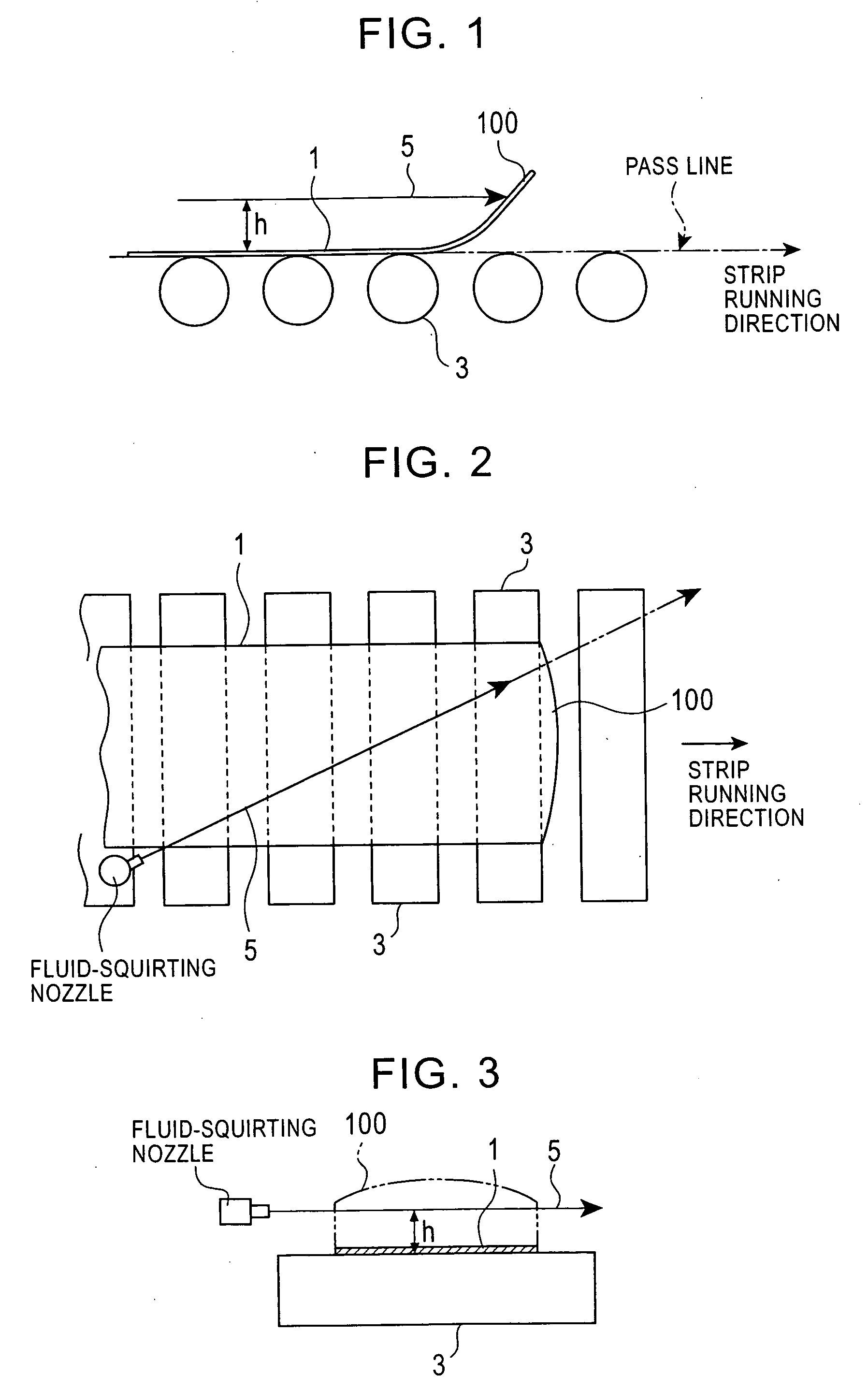
[0081]FIGS. 1, 2, and 3 show a squirting manner of a fluid jet 5 on a hot runout table in a production method according to an embodiment of the present invention. FIGS. 1, 2, and 3 are a side view, a plan view, and a front view, respectively, showing a hot runout table and a head end of a hot rolled strip conveyed by the hot runout table.

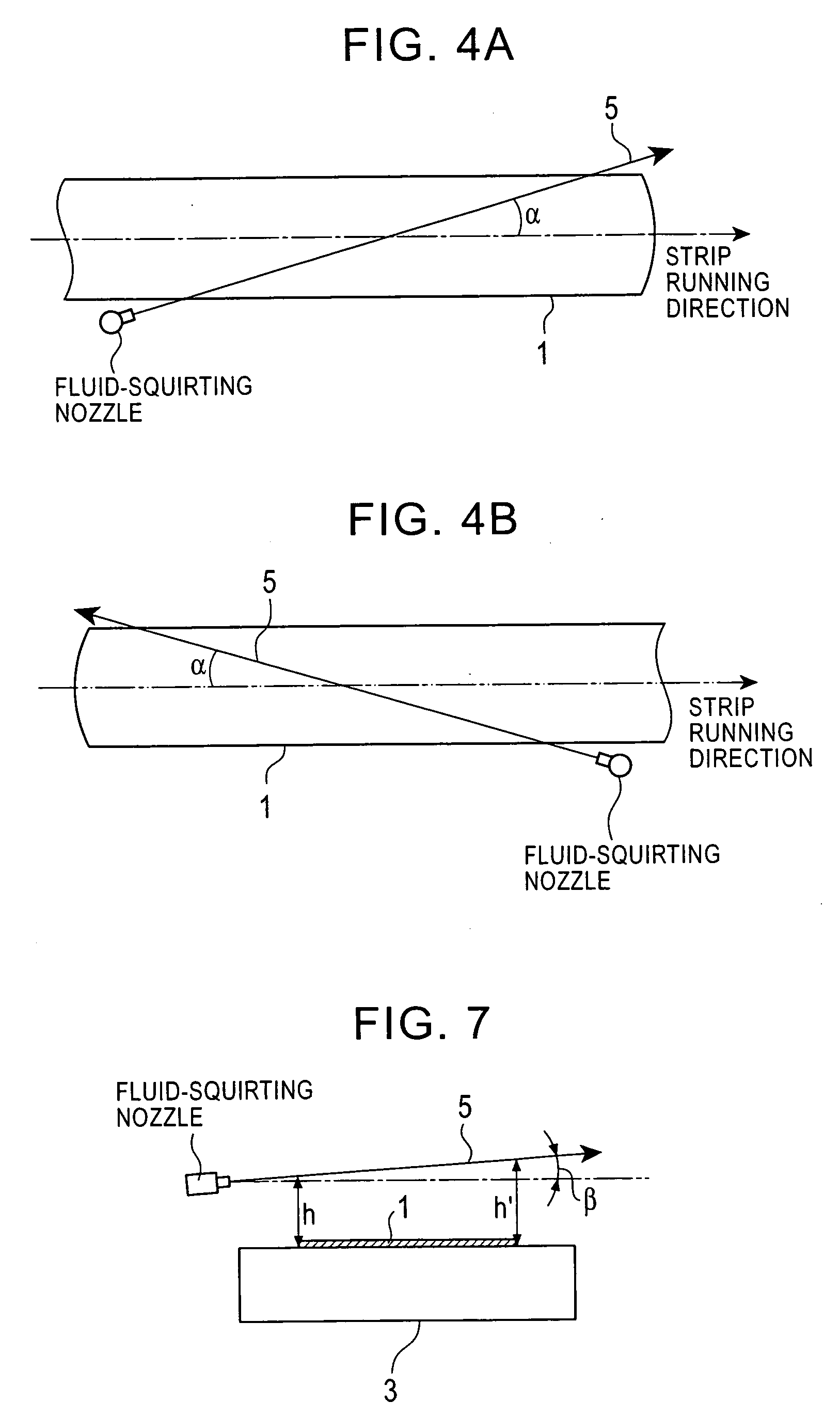
[0082] In the present invention, a beam-shaped fluid jet 5 is squirted above (an upper space) a hot rolled strip 1 conveyed by a hot r...


PUM

PropertyMeasurementUnit
Lengthaaaaaaaaaa
Lengthaaaaaaaaaa
Forceaaaaaaaaaa

Abstract

The present invention relates to a production method for a hot rolled strip in a hot rolling line. An object of the present invention is to ensure stable running of a hot rolled strip on a hot runout table, and to prevent excessive displacement of the hot rolled strip above a pass line, and, for example, a head folding defect and a tail folding defect resulting from the displacement. In the method of the present invention, a fluid jet is squirted above a hot rolled strip conveyed by a hot runout table so as to pass over the hot rolled strip running without touching a surface of the hot rolled strip running on a pass line (a strip-conveying surface of the hot runout table). A strip portion displaced upward from the pass line beyond a predetermined level collides with the fluid jet, and the displacement of the strip portion is thereby corrected. Since the fluid jet passes over the normally running hot rolled strip without touching therewith, the strip portion is properly prevented from being displaced by squirting the fluid jet.

Description

TECHNICAL FIELD [0001] The present invention relates to a production method and production system for a hot rolled strip in a hot rolling line. More particularly, the present invention relates to a method and system that smoothly conveys on a hot runout table a hot rolled strip rolled by a hot finishing rolling mill. Jumping or waving of the hot rolled strip on the hot runout table is eliminated by squirting water in a characteristic manner. BACKGROUND ART [0002] In a typical hot rolling line for producing hot rolled strips, a hot steel slab is rolled into a hot rolled strip by a hot rolling train including a hot roughing rolling mill and a hot finishing rolling mill, and the hot rolled strip is cooled by cooling water while running on a hot runout table composed of a plurality of table rolls, and is then coiled with a coiler, thus obtaining a hot rolled strip coil. [0003] In the hot rolling line, the hot rolled strip runs on the hot runout table in an unstable state on free tension...

Claims


Application Information

Patent Timeline
IPC IPC(8): B21B27/06B21B39/12B21B45/02
CPCB21B39/00B21B2273/02B21B45/0218B21B39/12
Inventor AOE, SHINICHIROKOBAYASHI, MASAKIHAYASHI, HIROMASAYUASA, DAIJIROTOMIYAMA, MASAJI
Owner JFE STEEL CORP
Features
  • R&D
  • Intellectual Property
  • Life Sciences
  • Materials
  • Tech Scout
  • Unparalleled Data Quality
  • Higher Quality Content
  • 60% Fewer Hallucinations
Learn More