Corkscrew suture anchor

a corkscrew and suture anchoring technology, applied in the field of corkscrew suture anchoring, can solve the problems of insufficient pull-out strength of the above-mentioned suture anchor, the type may present a limited range of specific fixation points, and certain known suture anchors also have a tendency to “back out”. , to achieve the effect of preventing the distal end from impinging, increasing the percentage of thread surface area, and increasing the pull-

Inactive Publication Date: 2006-01-05
ARTHREX
View PDF46 Cites 6 Cited by
  • Summary
  • Abstract
  • Description
  • Claims
  • Application Information

AI Technical Summary

Benefits of technology

[0013] The proximal end of the corkscrew suture anchor body has a hex drive head incorporating a slotted suture eye for receiving one or more pieces of suture. At the junction between the hex drive head and the central body, the circumference of the central body advantageously is larger than the outer circumferential dimension of the hex drive head. Accordingly, the enlarged body adjacent the hex drive head forms a hole sufficient to accommodate a hex driver disposed over the hex drive head. The hex driver is described more fully below. This allows the suture anchor to be at least partially countersunk below the surface of the bone upon installation by preventing impingement of the distal end of the hex driver on the bone surface.
[0014] Advantageously, the threads of the suture anchor of the present invention provide an increased percentage of thread surface area for each turn of the screw, as compared with known suture anchors, thus providing increased pull-out strength, and a decreased tendency for back-out. The increase in the surface area of the thread is achieved in part by increasing the ratio of the outer diameter of the threads to the inner diameter of the threads. Preferably, the ratio is between 2.25 and 2.75. Most preferably, the ratio of the outer diameter to the inner diameter is 2.5.
[0015] In addition, the suture anchor has a higher thread pitch than prior art screws, thus increasing the area of thread for each turn of the screw, which also leads to greater pull-out strength. Significantly, due to the increased pitch, fewer turns of the corkscrew screw thread are required to advance the suture anchor into position. Accordingly, the suture anchor is easy to install, and displaces less tissue material upon insertion than known suture anchors.
[0016] The pull-out strength and minimal tissue damage are enhanced by the relatively compressed cross-sectional aspect of the thread, particularly in relation to the broad axial faces of the threads. The distal and proximal faces of the threads preferably form a square or rounded break edge at the outer diameter of the thread. In addition, the thickness of the thread increases proximally, such that at least the most proximal flight is thicker than each of the more distal flights.
[0017] Increased back-out resistance is enhanced by surface features, such as radial ridges, on the top and / or bottom faces of the screw threads. The surface features augment the engagement between the thread surfaces and the surrounding tissue once the suture anchor is installed.
[0019] The driver is provided with a cleat on the side of the handle. Consequently, suture threaded through the cannulated driver can be wrapped around the cleat and fixed for shipping in a slot in the cleat using adhesive foam. One or more sutures, threaded through the suture anchor eye and up through the cannulated driver, can be pulled and secured around the cleat, whereby the suture is pinched under tension. Advantageously, the tensioned suture helps to hold the suture anchor in place at the distal tip of the driver. The suture anchor and driver assembly can be shipped, pre-loaded with suture, as a sterile, surgery-ready unit.

Problems solved by technology

Recent studies indicate, however, that the above-noted suture anchors may have problems related to inadequate “pull-out” strength.
These bone types may present a limited range of specific fixation points that are available to the surgeon.
Also, certain known suture anchors also have a tendency to “back out” of the implantation site.
Moreover, substantial bone loss is incurred simply upon installation of the above-described prior art suture anchors.
This problem is acute particularly during procedures that require removal or relocation of suture anchors.

Method used


Image

  • Corkscrew suture anchor
  • Corkscrew suture anchor
  • Corkscrew suture anchor

Examples


Embodiment Construction

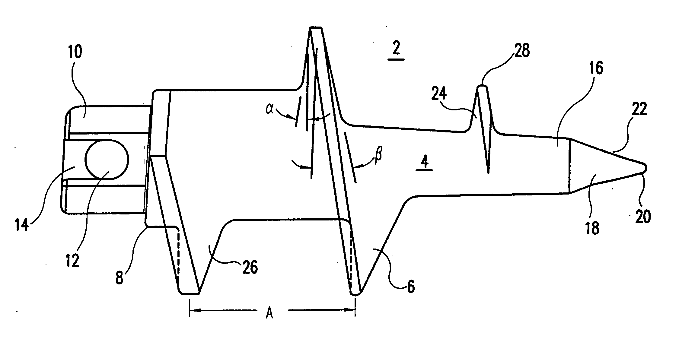
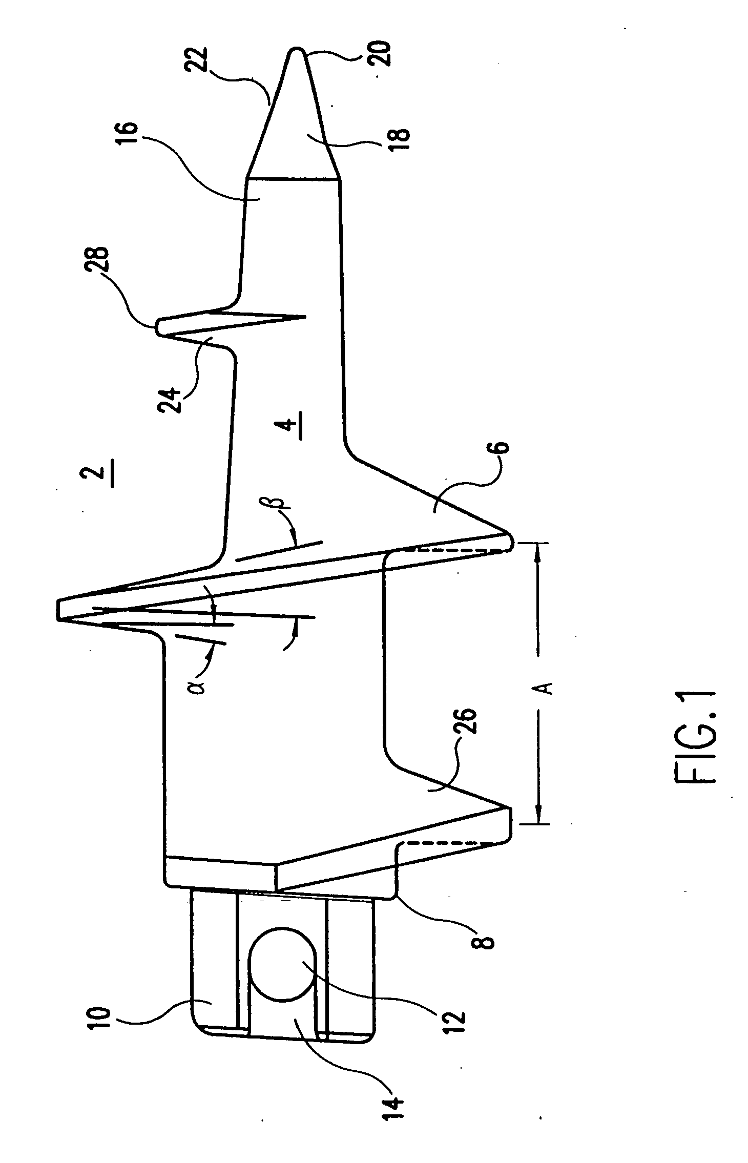
[0027] Referring to FIG. 1, the suture anchor 2 of the present invention includes a body 4 provided in the shape of a tapered cylinder. A continuous thread 6 wraps around body 4 in a clockwise direction, as shown.

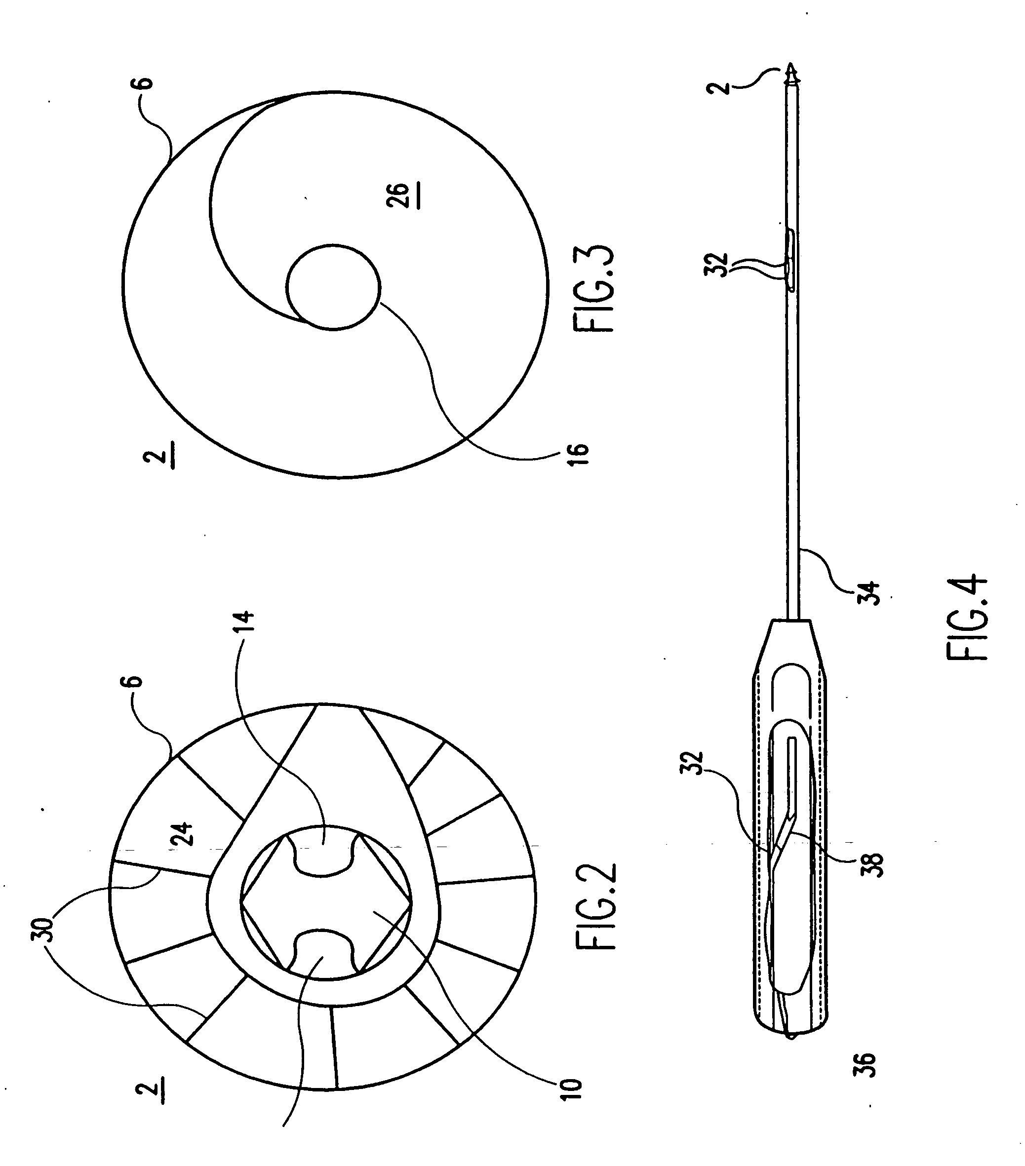
[0028] Suture anchor 2 is provided at a proximal end 8 of body 4 with hexagonal drive head 10 having a suture eye 12. The suture eye 12 preferably is in the form of an oval aperture in the drive head for holding at least one, and preferably two or more pieces of braided suture. Channels 14, also shown in FIG. 2, are formed along either side of the drive head 10 to accommodate the suture, such as when the suture anchor is held in a suture anchor driver, set forth more fully below.

[0029] A tip 18 is provided. Tip 18 terminates in a rounded point 20, which is approached by a concave, conically tapered surface 22. Conical taper 22 begins at the distal end of the screw thread, and features an angle of taper deeper than the taper of body 4.

[0030] The body preferably is formed ...


PUM


Abstract

A corkscrew suture anchor has a continuous thread spiraling around a tapering central core. At the distal end, the suture anchor terminates in a rounded point. At the proximal end of the suture anchor is an eye for receiving suture. The suture anchor has a large thread surface per turn of thread. Anti-backout ridges can be formed on the front and / or back faces of the threads. A driver for the suture anchor is provided, the driver including a shaft having a central axis, a length, a distal end, and a proximal end. The shaft is provided at its distal end with an opening aligned with the central axis of the shaft, for receiving the hexagonal proximal end of the suture anchor. One or more sutures threaded through the suture eye are threaded through the hollow tubular shaft. The suture is pulled into and captured by V-shaped notches on the proximal end of the handle to hold the suture anchor in place on the distal end of the driver under the tension of the captured sutures.

Description

[0001] This application is a continuation of U.S. application Ser. No. 10 / 285,553, filed Nov. 1, 2002, now U.S. Pat. No. 6,916,333, which is a continuation of U.S. application Ser. No. 09 / 823,988, filed Apr. 3, 2001, now U.S. Pat. No. 6,511,499, which is a continuation of U.S. application Ser. No. 09 / 588,065, filed Jun. 5, 2000, now U.S. Pat. No. 6,214,031, which is a continuation of U.S. application Ser. No. 08 / 954,206, filed Oct. 20, 1997, now U.S. Pat. No. 6,117,162, which is a continuation of U.S. application Ser. No. 08 / 905,393, filed Aug. 4, 1997, now abandoned. This application also claims the benefit of U.S. Provisional Application Ser. No. 60 / 023,011, filed Aug. 5, 1996.BACKGROUND OF THE INVENTION [0002] 1. Field of the Invention [0003] The present invention relates to an apparatus and method for anchoring surgical suture to bone. More specifically, the present invention relates to arthroscopic apparatus and methods for anchoring suture to cancellous bone using a suture anc...

Claims


Application Information

Patent Timeline
Patent Type & Authority Applications(United States)
IPC IPC(8): A61B17/56A61B17/00A61B17/04
CPCA61B17/0401A61B2017/00004Y10S606/916A61B2017/0414A61B2017/044A61B2017/0409
Inventor SCHMIEDING, REINHOLDGRAFTON, R. DONALDBRUNSVOLD, MARK
Owner ARTHREX
Why Eureka
Try Eureka