Material transportation system

a material transportation and automatic technology, applied in brake systems, transmissions, locomotives, etc., can solve the problems of increasing complexity of manufacturing processes, increasing complexity of products, and increasing complexity of manufacturing

Inactive Publication Date: 2005-05-03
MASSACHUSETTS INST OF TECH
View PDF64 Cites 174 Cited by
  • Summary
  • Abstract
  • Description
  • Claims
  • Application Information

AI Technical Summary

Benefits of technology

[0013]In accordance with the present invention, a material transportation system includes a magnetically attractive surface and one or more material transportation vehicles. Each of the one or more material transportation vehicles has two magnetic drive wheels, each coupled to the magnetically attractive surface. Each of the one or more material transportation vehicles also has a mechanical interface coupled to the two wheels via a chassis, and adapted to carry material. Each of the one or more material transportation vehicles has a wheel control system that controls its motion, including its pitch. The one or more material transportation vehicles can be coupled to a collision avoidance and traffic control system capable of causing the one or more material transportation vehicles to avoid collisions with one another and to avoid other obstacles.

Problems solved by technology

At the same time, many products have become increasingly complex and, therefore, require complex manufacturing processes.
Though manufacturing has become increasingly complex, manufacturing must maintain profitability.
In contrast, manual material transportation is costly and slow.
Furthermore, human factors limit the ease by which a manual material transportation arrangement can be expanded and contracted to meet a variation in manufacturing throughput or product.
Hospitals and clinical labs lack an appropriate automated material handling system, yet are facing increases in the amount of material that requires transport.
Some hospitals have installed pressurized air-chute systems for transporting documents, yet these systems are expensive, limited in path extent, require operator attention at each transfer, and are unable to transport the variety of payloads mentioned above.
Many general use automated material handling systems, though used for a variety of material handling tasks, still can only be applied to a specific industry.
While a particular automated material handling (AMH) system might make economic sense for one particular industry, often the same system is not the optimum choice for a different industry.
However, even a related industry, the Testing, Assembly & Packaging (TAP) industry that compliments IC manufacturing (or is a separate part of a single semiconductor fabrication facility), is not able to use the clean room AMH systems because they do not meet the economic constraints and flexibility requirements of the TAP operations.
Most existing AMH systems are specifically tailored to particular applications, rendering them of little general use.

Method used


Image

  • Material transportation system
  • Material transportation system
  • Material transportation system

Examples


Embodiment Construction

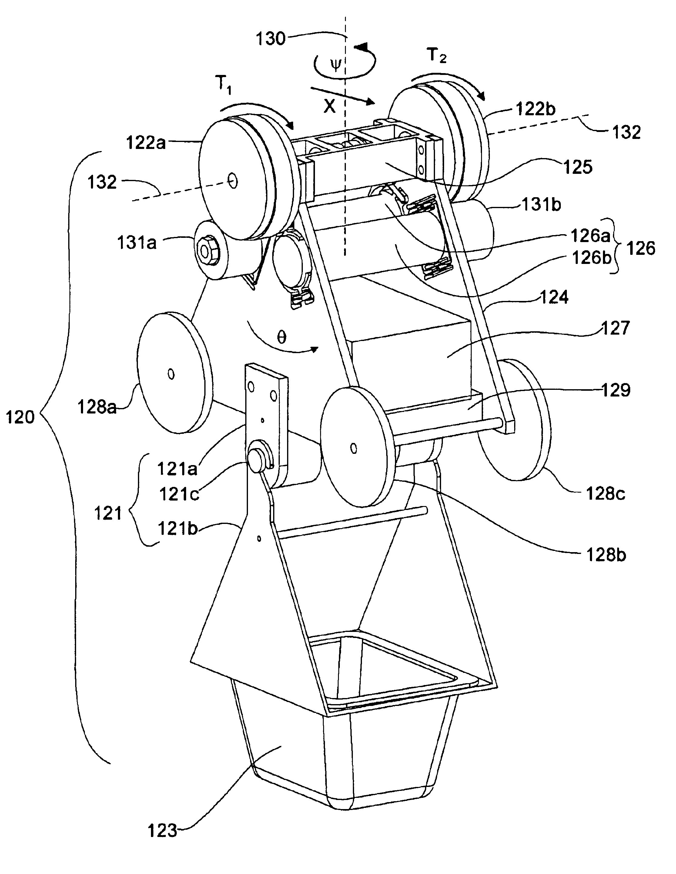
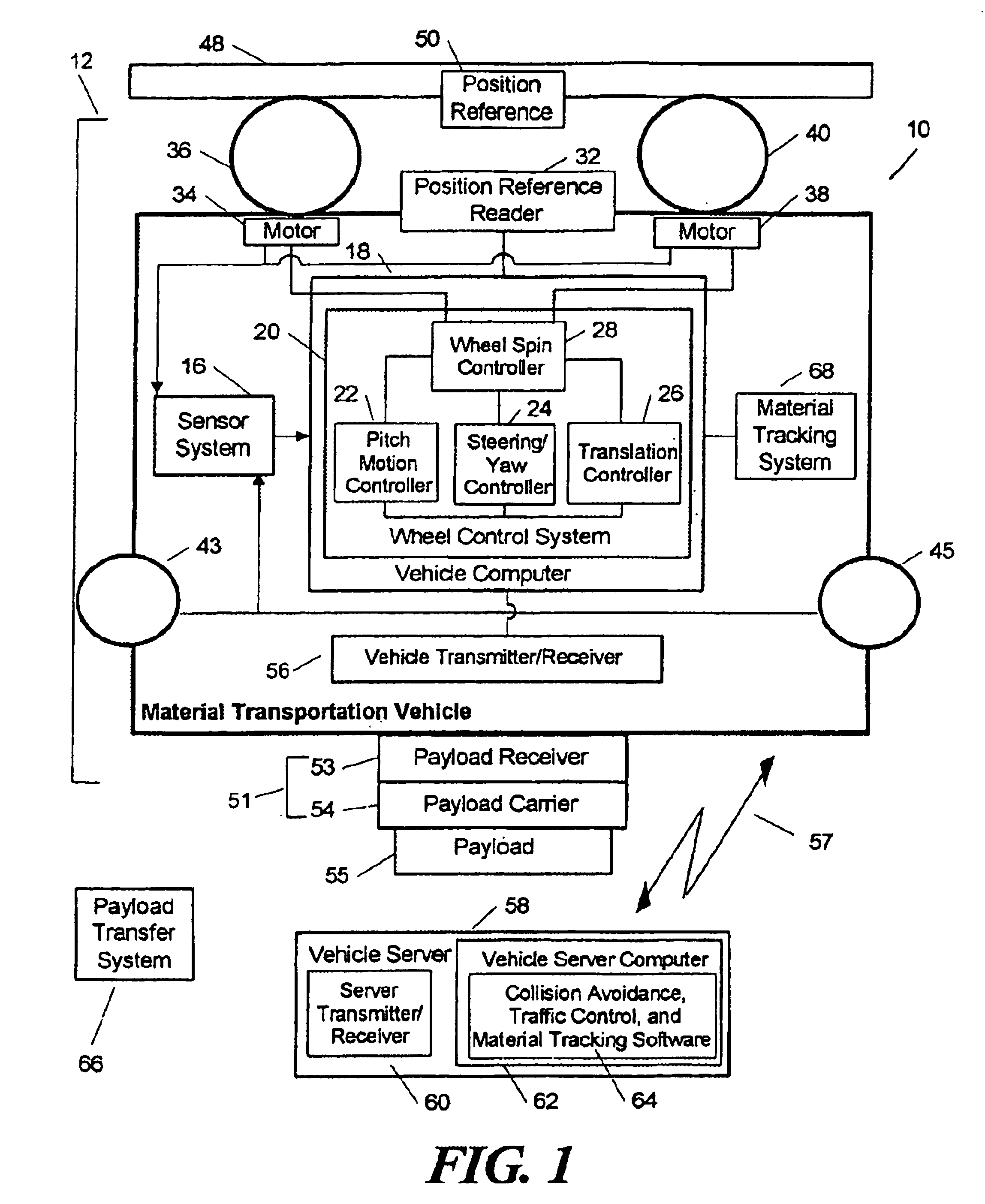
[0027]Referring now to FIG. 1, a material transportation system 10 includes one or more material transportation vehicles 12, only one of which is shown in FIG. 1 for simplicity in the drawing and ease of explanation. The material transportation vehicle 12 includes a sensor system 16 coupled to a vehicle computer 18. The sensor system 16 can include a variety of sensors, including, but not limited to, accelerometers, rate gyros, inclinometers, optical encoders, and proximity sensors.

[0028]The vehicle computer 18 includes a wheel control system 20, which includes a vehicle pitch motion controller 22, a vehicle steering / yaw controller 24, and a vehicle translation controller 26, each of which are coupled both to each other and to a wheel spin controller 28. The wheel spin controller 28 is coupled to a first wheel motor 34 that drives a first wheel 36, and to a second wheel motor 38 that drives a second wheel 40. The wheel motors 24, 38 are coupled to the sensor system 16. Each of the w...


PUM


Abstract

A material transportation system includes one or more material transportation vehicles, each having magnetic wheels coupled to a magnetically attractive surface that can include a ceiling, a wall, a floor, and/or a transition region. The material transportation vehicles are adapted to carry material from place to place. Each material transportation vehicle has sensors and motor controls that reduce swing motion of the material transportation vehicle and the material coupled thereto. A collision avoidance and traffic control system prevents collisions between the one or more material transportation vehicles.

Description

CROSS REFERENCE TO RELATED APPLICATIONS[0001]This application claims the benefit of U.S. Provisional Application No. 60 / 346,491 filed Jan. 7, 2002 which application is hereby incorporated herein by reference in its entirety.STATEMENT REGARDING FEDERALLY SPONSORED RESEARCH[0002]Not Applicable.FIELD OF THE INVENTION[0003]This invention relates generally to automated material transportation systems and more particularly to a trackless automated material transportation system with vehicles having magnetic wheels.BACKGROUND OF THE INVENTION[0004]In many areas of manufacturing, both production volume and product variety have increased. At the same time, many products have become increasingly complex and, therefore, require complex manufacturing processes. Though manufacturing has become increasingly complex, manufacturing must maintain profitability. Profitable manufacturing requires high yields, shorter lead times, and improved equipment utilization.[0005]Automated material transportatio...

Claims


Application Information

Patent Timeline
Patent Type & Authority Patents(United States)
IPC IPC(8): B60L13/04B61C11/00B60T7/16
CPCB60L13/04B61C11/00B60T7/16
Inventor SLOCUM, ALEXANDER H.AWTAR, SHORYAHART, ANASTASIOS JOHN
Owner MASSACHUSETTS INST OF TECH
Why Eureka
Try Eureka