Rotationally supporting structure of vehicle's drag-reducing apparatus

a technology of rotating support and vehicle, which is applied in the direction of roofs, transportation and packaging, vehicle arrangements, etc., can solve the problems of large drag caused, large inconvenience in use, and large magnitude of drag, and achieve the effect of reducing the formation of drag and enhancing the practicability and convenience of invention

Active Publication Date: 2012-06-12
SMART ENERGY
View PDF31 Cites 25 Cited by
  • Summary
  • Abstract
  • Description
  • Claims
  • Application Information

AI Technical Summary

Benefits of technology

[0007]Therefore, in order to solve the aforementioned problems, the invention is mainly to provide a rotationally supporting structure of a vehicle's drag-reducing apparatus, in which the diversion body can be moved to a side far away from the tail end of the vehicle by rotating the rotary piece, such that the hindrance for opening the rear door at the tail end of the vehicle can be avoided, even when there is an arrangement of the diversion body.
[0009]Compared with prior arts, the invention further possesses the following functions and merits. First of all, a rotationally supporting structure of a vehicle's drag-reducing apparatus according to the present invention is to vertically arrange a deflector at the tail end of the lateral surface of the vehicle body, such that the direction of the airflow flowing through the deflector is changed and the airflow is guided to the back of the vehicle body, whereby a formation of drag is thus reduced. Secondly, the deflector arranged at the tail end of the vehicle body can be rotated 180 degrees by a rotary piece to a side far away from the tail end of the vehicle, whereby the hindrance for opening the rear door at the tail end of the vehicle body can be avoided, which really enhances the practicability and convenience of the invention.

Problems solved by technology

Although the deflector can reduce the influence caused by the airflow flowing at front and back of the vehicle body, there is still a large magnitude of drag caused by the airflow flowing across the side lateral surfaces of the vehicle body, when the car is running.
However, when the vehicle is stopped, the deflector vertically arranged at the tail end of the lateral surface of the vehicle body becomes a hindrance for opening the rear door.
Therefore, the deflector has to be dismantled before opening the rear door, which causes a lot of inconvenience in terms of usage.

Method used


Image

  • Rotationally supporting structure of vehicle's drag-reducing apparatus
  • Rotationally supporting structure of vehicle's drag-reducing apparatus
  • Rotationally supporting structure of vehicle's drag-reducing apparatus

Examples


Embodiment Construction

[0016]In cooperation with attached drawings, the technical contents and detailed description of the present invention are described thereinafter according to an embodiment, not used to limit its executing scope. Any equivalent variation and modification made according to appended claims is all covered by the claims claimed by the present invention.

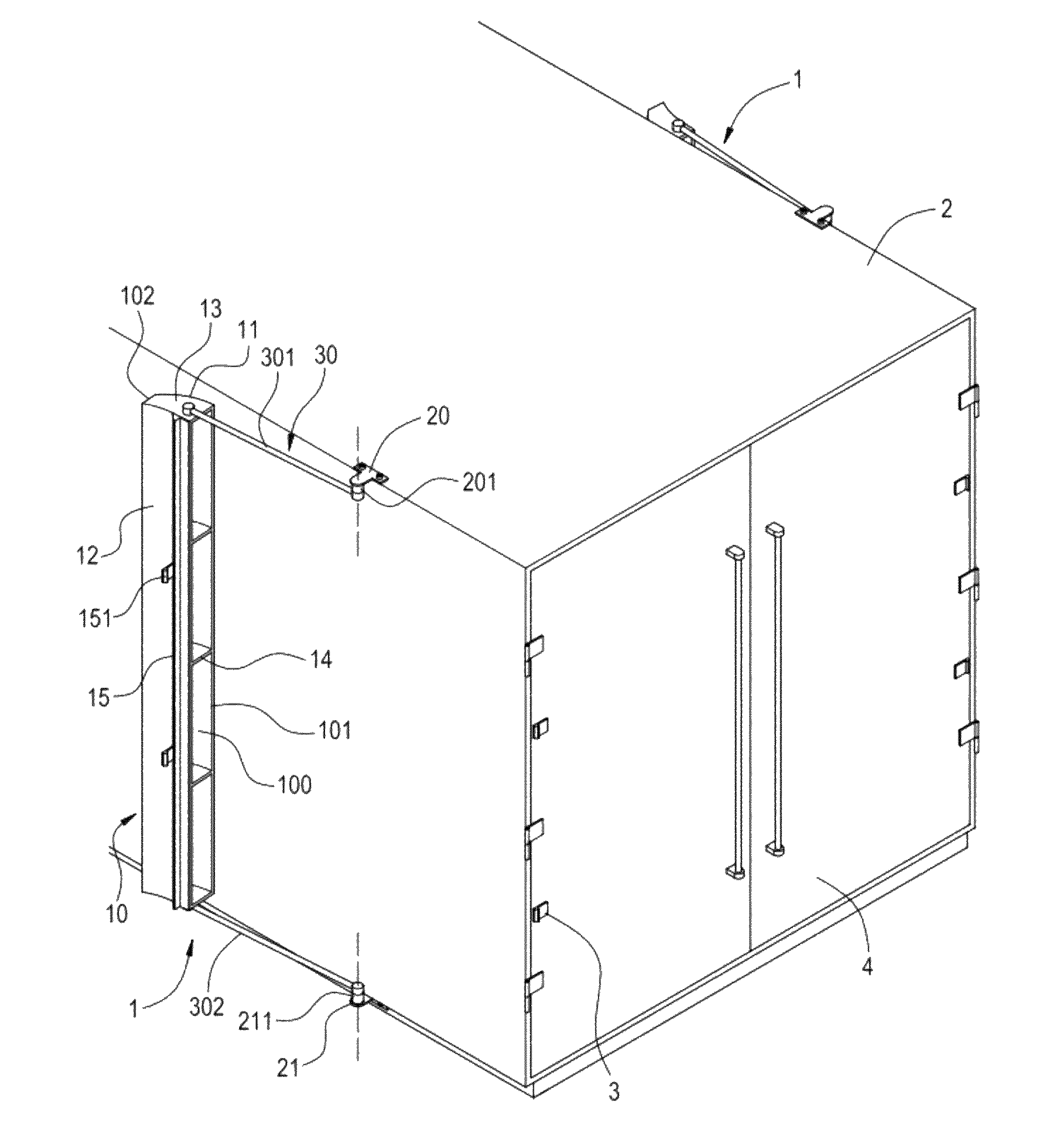
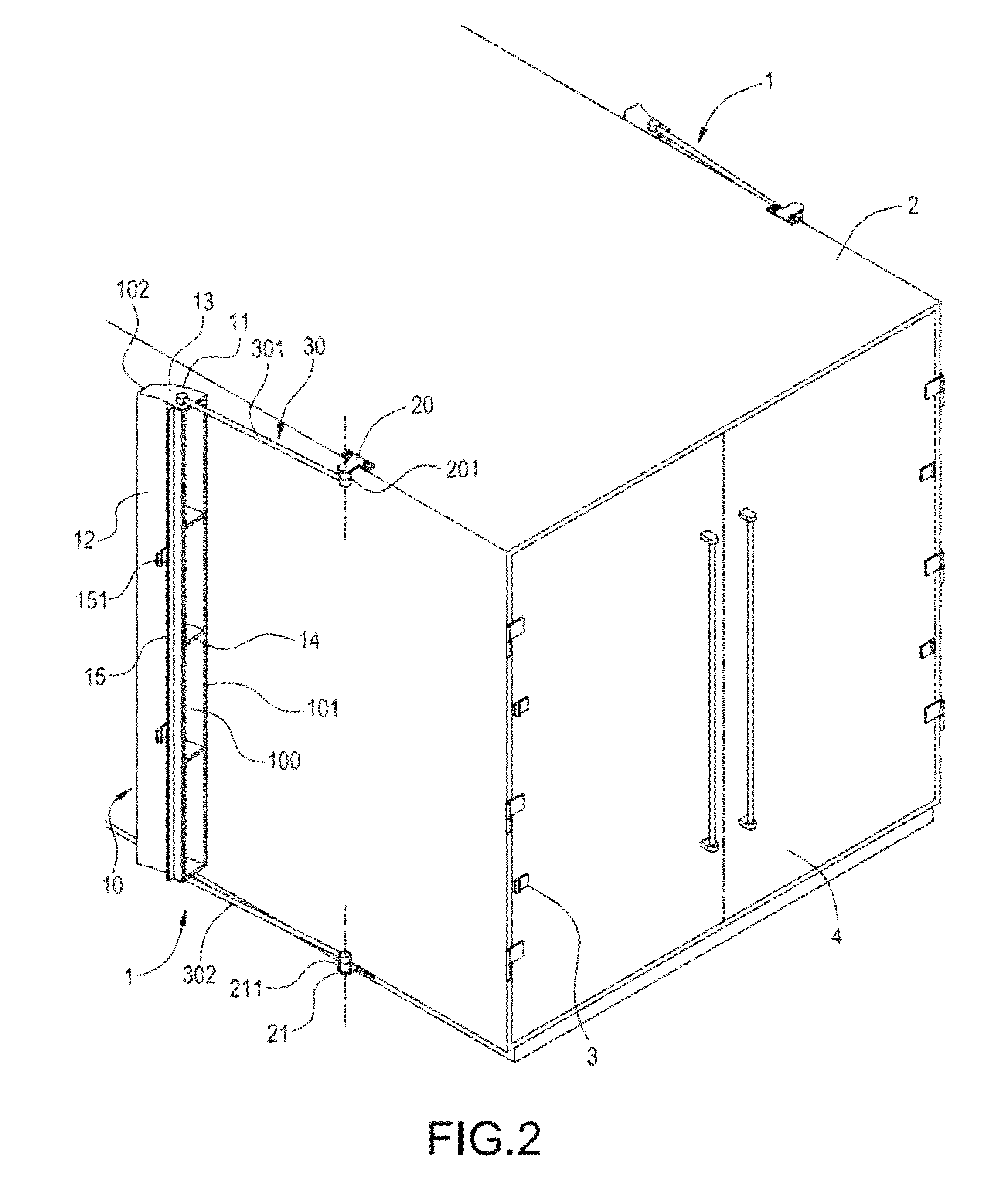
[0017]Please refer to FIG. 1 and FIG. 2, which are two illustrations respectively showing a vehicle's drag-reducing apparatus arranged at the vehicle body. The vehicle's drag-reducing apparatus 1 according to the present invention is arranged at two lateral surfaces of a vehicle body 2 and includes a diversion body 10 and a rotary piece 30.

[0018]In this embodiment, the diversion body 10 is a long frame body positioned at a lateral surface of the vehicle body 2. The frame body is comprised of an outer deflector 11, an inner deflector 12 disposed by corresponding to the outer deflector 11 and two lateral deflectors 13 connecting the outer de...


PUM


Abstract

A vehicle's drag-reducing apparatus, adapted to be arranged at the tail end of a vehicle, includes a diversion body positioned at the lateral surface of the vehicle and a rotary piece. The airflow flowing across the lateral surface of the vehicle body is guided to the tail end of the vehicle by the diversion body. One end of the rotary piece is pivoted to the vehicle body, while another end is fixed to the diversion body. Rotating the rotary piece will bring along the diversion body to be abutted against the tail end of the vehicle body or to be moved to the position far away from the tail end of the vehicle body. Thereby, the opening of the rear door at the tail end of the vehicle won't be hindered, even where there is an arrangement of the diversion body.

Description

BACKGROUND OF THE INVENTION[0001]1. Field of the Invention[0002]The present invention in general relates to airflow diversion structures, in particular, to an airflow diversion structure capable of reducing the drag of a running vehicle.[0003]2. Description of Prior Art[0004]When a vehicle is running in high speed, in order to reduce the unnecessary fuel consumption and the drag generated from the influence of the airflow, a commonly adapted solution is to install an airflow deflector on top of the vehicle. Through guiding the airflow by the deflector, the drag and the fuel consumption are reduced. According to prior arts, the deflector is installed at the tail end of the top of a vehicle, in particular, a large vehicle, such as a tractor trailer. When the vehicle is driven on the road, the flowing angle of the airflow formed at the windward sides can be changed, such that the drag generated from the running of the vehicle can be reduced.[0005]Although the deflector can reduce the i...

Claims


Application Information

Patent Timeline
Patent Type & Authority Patents(United States)
IPC IPC(8): B62D35/00
CPCB62D35/001Y10S180/903
Inventor CHEN, SHIH-HSIUNG
Owner SMART ENERGY
Why Eureka
Try Eureka