Insertion valve and installation method

a technology of valves and installation methods, which is applied in the direction of valve housings, functional valve types, transportation and packaging, etc., can solve the problems of weakened pipes, weakened pipes, and valves in the line containing fluid under pressure, and achieve the effects of less complex, less expensive, and less vulnerable to tension

Inactive Publication Date: 2007-06-05
OCCLUDE PROD
View PDF31 Cites 28 Cited by
  • Summary
  • Abstract
  • Description
  • Claims
  • Application Information

AI Technical Summary

Benefits of technology

[0015]The valve body includes a radially outwardly facing access opening through which workmen cut a gate-receiving gap in the existing pipe with a radially advancing hole saw. After cutting the gate-receiving gap in the existing pipe (a gap that results in completely separate upstream and downstream portions of the pipe), the workmen remove the hole saw and insert a gate form of valve-stopping element through the access opening into an operative position within the valve body. The gate can be moved to a closed position in which it extends through the gap in the pipe into fluid-tight engagement of the mating valve body.
[0016]The structure and methodology of the instant invention are less complex and less costly than rotatable insertion equipment. The structure is sturdy and can avoid many obstacles in the field that may hinder rotating circumferentially about the pipe. An oversize valve body and oversized hole saw solve the problem.
[0017]In addition, the sturdy, non-rotating structure is less vulnerable to tensions occurring as the pipe is cut. As a gap is created in an existing pipeline, tremendous tensions commonly occur that can cause binding and otherwise disable rotational valve body structure. Pipeline tension is common in outdoor and indoor pipelines, caused by compaction of earth and shifting earth against buried pipelines and the hanging weight and expansion and / or contraction of indoor pipelines by temperatures and flows.
[0018]Existing rotatable insertion equipment uses multiple separate seal-off housings held in rotational relationship to each over a pipe in order to form a gap in the pipe. The resulting structure is vulnerable to the tensions that occur as the pipe is cut. The instant invention overcomes this because the valve body is a rigid structure that does not have separate parts that are rotatable about the valve body axis relative to each other. The bonnet-supporting flange is not rotatable about the valve body axis relative to the first and second ends of the valve body. A strong, rigid valve body results, and it can be fully welded or fused and otherwise mechanically restrained prior to forming a gap in the pipeline. The following illustrative drawings and detailed description make the foregoing and other objects, features, and advantages of the invention more apparent.

Problems solved by technology

The task of inserting a valve in a line containing fluid under pressure (e.g., a municipal water line or natural gas line) without otherwise shutting down the line during the insertion can be expensive, inconvenient, and time consuming.
One problem with the rubber plunger technique is that success of the valving apparatus depends on the internal size and condition of the pipe.
In addition, an old, corroded or otherwise damaged and weakened pipe is subject to being broken.
Furthermore, pushing a plug through a tapped hole subjects the rubber gate to being cut by the sharp edges of the hole cut in the pipe each time the gate is opened and closed.

Method used


Image

  • Insertion valve and installation method
  • Insertion valve and installation method
  • Insertion valve and installation method

Examples


second embodiment

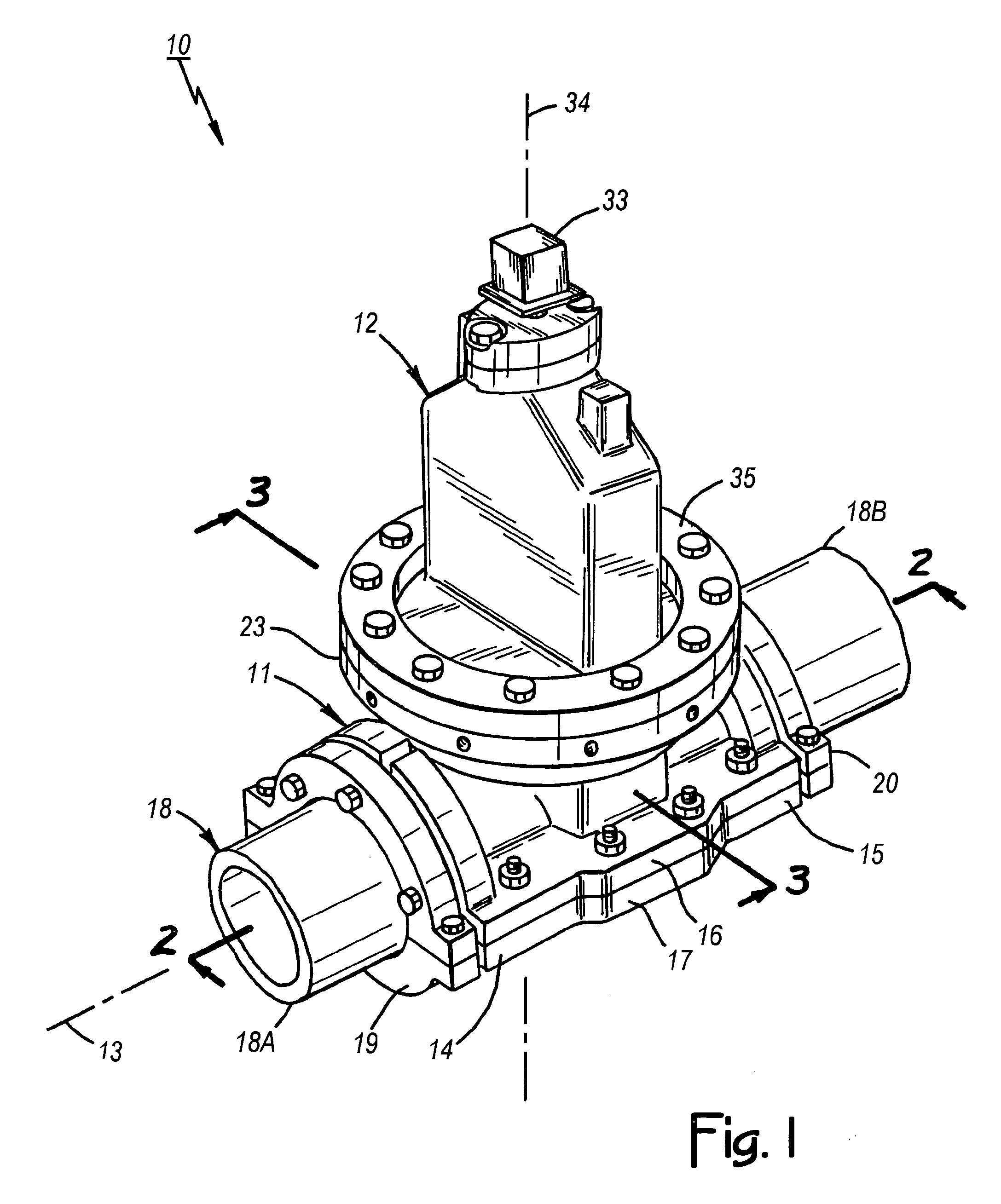
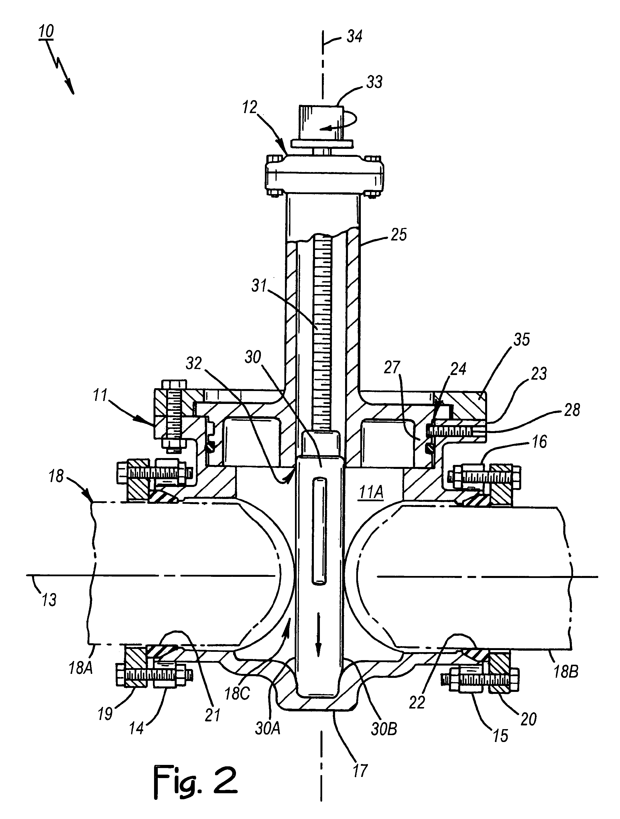
[0072]Various alternative valve structures are shown in FIGS. 8 through 22. FIG. 8 shows the invention in the form of a valve assembly 100. The valve body 101 of the valve assembly 100 illustrates that it may be installed by welding (e.g., weld at reference numeral 102) or be bolted together (e.g., as illustrated at reference numeral 103). The flange-mating portion 104 of the bonnet 105 mounts over the access opening 106 in a fluid-tight fit without fitting into the access opening. The bonnet-to-gate sealing surface is provided by a sealing member 107 that is removably attached by bolting internally. The sealing member 107 also provides an opening (a gate opening) through which the gate 108 extends from the bonnet 105 in a fluid-tight fit.

third embodiment

[0073]FIG. 9 shows the invention in the form of a valve assembly 110. It is similar to the valve assembly 100, but the bonnet 111 bolts internally to a flange-mating portion 112, and the flange-mating portion 112 bolts onto the flange 113, over the access opening 114, without fitting into the access opening. The flange-mating portion 112 provides an opening (a gate opening) through which the gate 115 extends in a fluid-tight fit. It also provides a bonnet-to-gate sealing surface. Having the bonnet 111 so it can be unbolted, allows installing a tapered gate during manufacturing that is wider at one end than the bonnet-to-gate sealing surface, thereby creating a tighter seal.

fourth embodiment

[0074]FIGS. 10A and 10B show the invention in the form of a valve assembly 120. The valve body 121 is installed by welding, although it could be assembled using bolts or other suitable means. The flange-mating portion 122 of the bonnet 123 fits into the access opening 124. Bonnet-to-gate sealing is achieved by a sealing member 125 that is mounted on the flange-mating portion 122 with a set screw arrangement, although segmented rings can be used instead. The gate 126 extends through the sealing member 125.


PUM


Abstract

A valve assembly for insertion in a pipe containing fluid under pressure includes a valve body adapted to be assembled over the pipe and a valve-stopping mechanism that mounts on the valve body. The hollow valve body interior and an access opening in the valve body are sufficiently large to receive a hole saw element no smaller than the outside diameter of the pipe as installers advance the hole saw element radially through the access opening to form a gap in the pipe. The valve-stopping mechanism includes a gate with a cross sectional area greater than the pipe that mates with the valve body interior so that the gate can be advanced radially through the gap in the pipe into direct fluid-tight contact of the valve body in order to thereby stop the flow of fluid through the pipe.

Description

CROSS REFERENCE TO RELATED APPLICATION[0001]This application is a continuation in part of U.S. patent application Ser. No. 10 / 376,552 filed Feb. 28, 2003, now U.S. Pat. No. 6,776,184 B1 issued Aug. 17, 2004.BACKGROUND OF THE INVENTION[0002]1. Technical Field[0003]This invention relates generally to procedures and equipment for stopping an existing water, sewer, gas, or other line containing fluid under pressure, and more particularly to a valve assembly and installation method for inserting a valve in a line without otherwise shutting down the line during the insertion.[0004]2. Description of Related Art[0005]The task of inserting a valve in a line containing fluid under pressure (e.g., a municipal water line or natural gas line) without otherwise shutting down the line during the insertion can be expensive, inconvenient, and time consuming. Yet the need to do so is commonplace. Damaged fire hydrants, for example, frequently need replacement and doing so quickly in a cost-effective ...

Claims


Application Information

Patent Timeline
Patent Type & Authority Patents(United States)
IPC IPC(8): F16K43/00F16K27/04
CPCF16K3/0272F16K3/12F16K27/044F16K27/047F16K43/001F16L41/06F16L55/105Y10T137/6123
Inventor MAICHEL, JEFFREY L.SOVILLA, THOMAS A.
Owner OCCLUDE PROD
Why Eureka
Try Eureka