Flight passenger seat with an integrated spring element

a passenger seat and spring element technology, applied in the field of seats and seat groups for airplanes, can solve the problems of large time expenditure, manual operation of the folding mechanism, and the possibility of deadlock, and achieve the effect of high design freedom

Active Publication Date: 2005-12-08
AIRBUS OPERATIONS GMBH
View PDF57 Cites 24 Cited by
  • Summary
  • Abstract
  • Description
  • Claims
  • Application Information

AI Technical Summary

Benefits of technology

[0015] According to a further exemplary embodiment of the present invention, a first reset element may be integrated in the volume formed by the seat element, and a second reset element may be integrated in the volume formed by the back element. The seat element and the back element may have a shared rotating or pivoting axis. The reset elements are arranged in such a way that they engage at a distance from the respective rotating axis. Due to these reset elements engaging tangentially to the center of rotation, when pivoting the seat element as well as the back element, a torque is applied which tends to inhibit the pivoting movement as soon as a release occurs. In order to compensate the pivoting movements of the reset elements occurring during the pivoting movements, for adjusting to the circumstances of articulation which are modified depending on the position, the ends of the reset elements are punctually mounted in bearings. This arrangement may allow for

Problems solved by technology

There are models, at which the folding mechanism has to be operated manually in a disadvantageous manner.
In case of automatically pivoting seat areas, it proves to be disadvantageously that, for example, not all seats of a seat group are pivotable, or, on the other hand, elements of a seat which are, for example, required for the folding mechanism, extend into the space cleared due to the pivoting in an obstructing manner.
One disadvantage of a passenger cabin having a large number of seats is that due to the narrow cabin's l

Method used


Image

  • Flight passenger seat with an integrated spring element
  • Flight passenger seat with an integrated spring element
  • Flight passenger seat with an integrated spring element

Examples


Embodiment Construction

[0034] In the following description, for the same or corresponding elements, the same reference numerals are used.

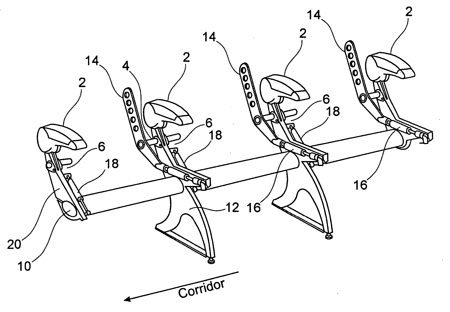
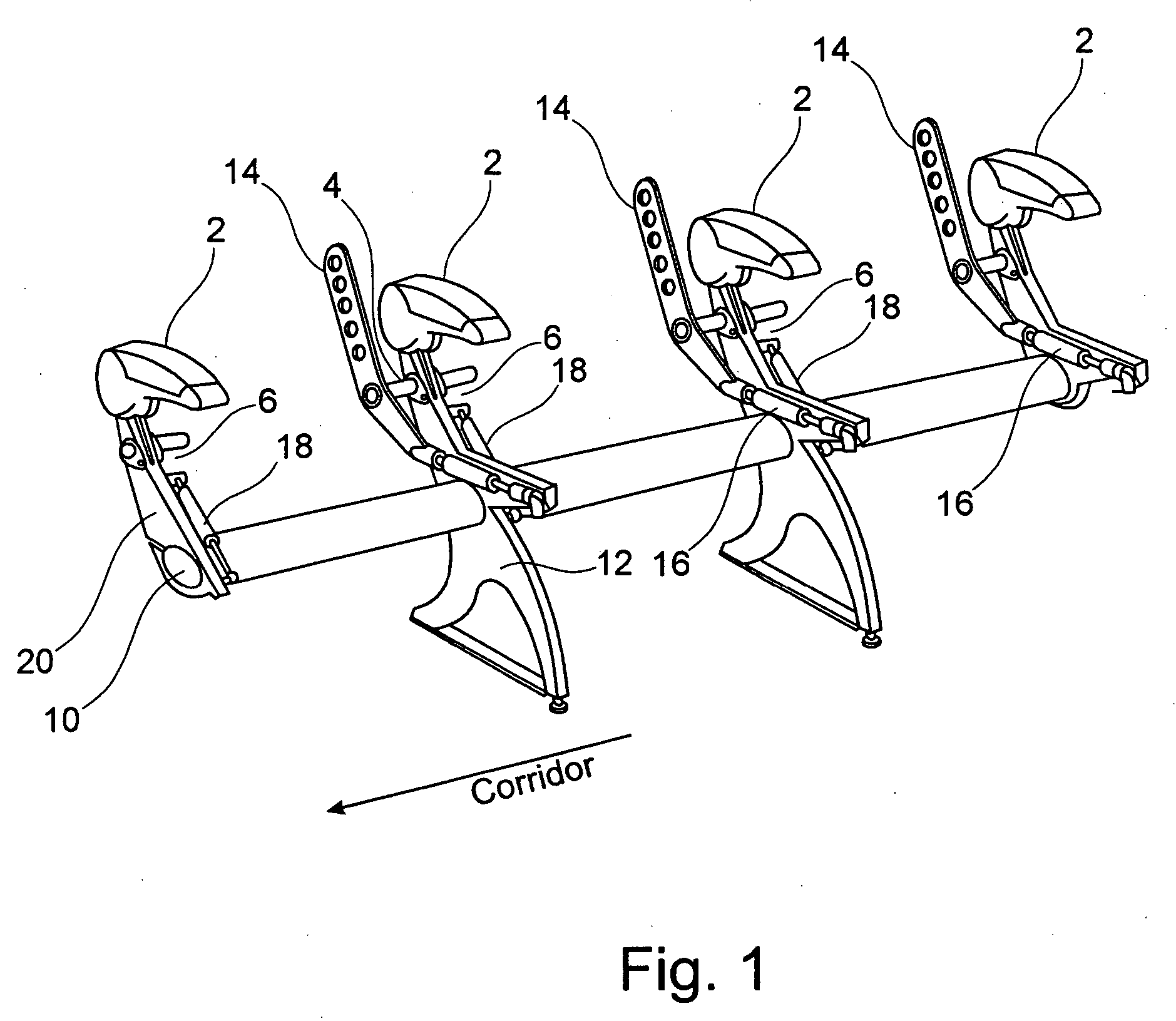
[0035]FIG. 1 shows a schematic three dimensional side view of a frame of a seat group according to the present invention. This frame includes a continuous support spar 10 supported by two frame feet. Further, the seat frame is connected with seat dividers 20, which laterally grasp around the back elements. Arm rests 2 are mounted at the top of the seat dividers 20. The drawing in FIG. 1 shows a frame for a seat group, at the left side of which (in the shown exemplary embodiment) there is the corridor of an airplane. Mirror-inverted, this seat group would be applied at the other side of the corridor. For clearing traffic areas, appliances are provided, which are adapted to pivoting of seat elements (the seat elements are not shown in FIG. 1). A second reset element 18 acts on a pivoting lever 6, connected with a support bolt 4 in a torque proof manner. At the support bol...


PUM


Abstract

The present application describes a flight passenger seat for an airplane. According to an embodiment example of the present invention, the flight passenger seat comprises a back element, a seat element and an arm rest. Seat element, back element and arm rest may be able to be pivoted. Reset elements for an automatic pivoting are integrated into the back element and the seat element in such a way that they occupy as little space as possible of a traffic area, which has to be kept clear. In an advantageous manner, this allows for an enlargement of a traffic area in an airplane and thereby may effectuate a reduction of a “turn around” time of an airplane.

Description

CROSS-REFERENCE TO RELATED APPLICATIONS [0001] This application claims the benefit of the filing date of U.S. Provisional Patent Application No. 60 / 598,265 filed Aug. 3, 2004, the disclosure of which is hereby incorporated herein by reference.FIELD OF THE INVENTION [0002] The present invention relates to a flight passenger seat, e.g. for a passenger cabin of a passenger airplane. In particular, the present invention relates to a seat and a seat group for an airplane. BACKGROUND OF THE INVENTION [0003] Conventional flight passenger seats for airplanes have a support frame with either a seat area fixedly disposed thereon or a pivoting seat area. In the region of the rear edge of the seat area, a back rest is disposed. In airplanes, the passenger seats preferably form seat rows, wherein two or several adjacently disposed passenger seats or seats may be combined to one seat group supported by one shared support frame. Nowadays, in case of seats having a pivoting seat area, there may be ...

Claims


Application Information

Patent Timeline
IPC IPC(8): A47C7/56A47C7/54B60N2/02B60N2/22B60N2/30B60N2/90B64C1/00B64D11/06
CPCB60N2/22B64D11/064B64D11/06B60N2/4435B60N2/933B64D11/0644
Inventor SCHUMACHER, MARKUSMUIN, ANDREW
Owner AIRBUS OPERATIONS GMBH
Why Eureka
Try Eureka