Developer Supply Device and Image Forming Apparatus

a technology of developing equipment and supply device, which is applied in the direction of electrographic process equipment, instruments, optics, etc., can solve the problems of affecting the collection of developer, the apt stagnation of developer which has reached the downstream transport surface, and the high possibility of dirtying of paper and components of the apparatus

Inactive Publication Date: 2009-07-09
BROTHER KOGYO KK
View PDF5 Cites 26 Cited by
  • Summary
  • Abstract
  • Description
  • Claims
  • Application Information

AI Technical Summary

Benefits of technology

[0014]According to the above-mentioned configuration, the developer is transported on the upstream transport surface at a relatively low upstream transport speed. Thus, when the developer transported on the upstream transport surface does not adhere to the developer carrying surface (e.g., the circumferential surface of a developing roller) and reaches a downstream end portion of the upstream transport surface, a speed at which the developer flies out toward a space in the vicinity of the developing area is lowered. Accordingly, an area in which the developer scatters can be prevented from becoming excessively large. As a result, there can be avoided a problem in that the scattered developer dirties paper and component members of the apparatus.
[0036]Furthermore, even when the developer which does not adhere to the latent image forming surface and reaches the downstream transport surface is relatively large in amount, since the developer on the downstream transport surface is transported at a relatively high downstream transport speed, there can be prevented the stagnation of developer at an upstream end portion of the downstream transport surface. Thus, a hindrance to the collection of the developer can be avoided. As a result, since an increase in the amount of developer scattering in a space in the vicinity of the developing area can be restrained, adhesion of the developer to the latent image forming surface at improper positions can be prevented, thereby avoiding a deterioration in the quality of an image formed in developer on the latent image forming surface.

Problems solved by technology

Thus, the scattering developer has a high possibility of dirtying paper and component members of the apparatus.
However, when the transport speed of developer on the downstream transport surface (downstream transport speed) is low, the developer which has reached the downstream transport surface is apt to stagnate at an upstream end portion of the downstream transport surface.
Thus, the collection of developer is apt to be hindered.
As a result, the developer is highly likely to adhere to the latent image forming surface at improper positions, thereby deteriorating the quality of an image formed in developer on the latent image forming surface.
As mentioned above, a conventional image forming apparatus has the risk of occurrence of the following problems.
When the transport speed of developer is lowered uniformly, the quality of an image formed in developer on the latent image forming surface deteriorates.

Method used


Image

  • Developer Supply Device and Image Forming Apparatus
  • Developer Supply Device and Image Forming Apparatus
  • Developer Supply Device and Image Forming Apparatus

Examples


Embodiment Construction

Configuration

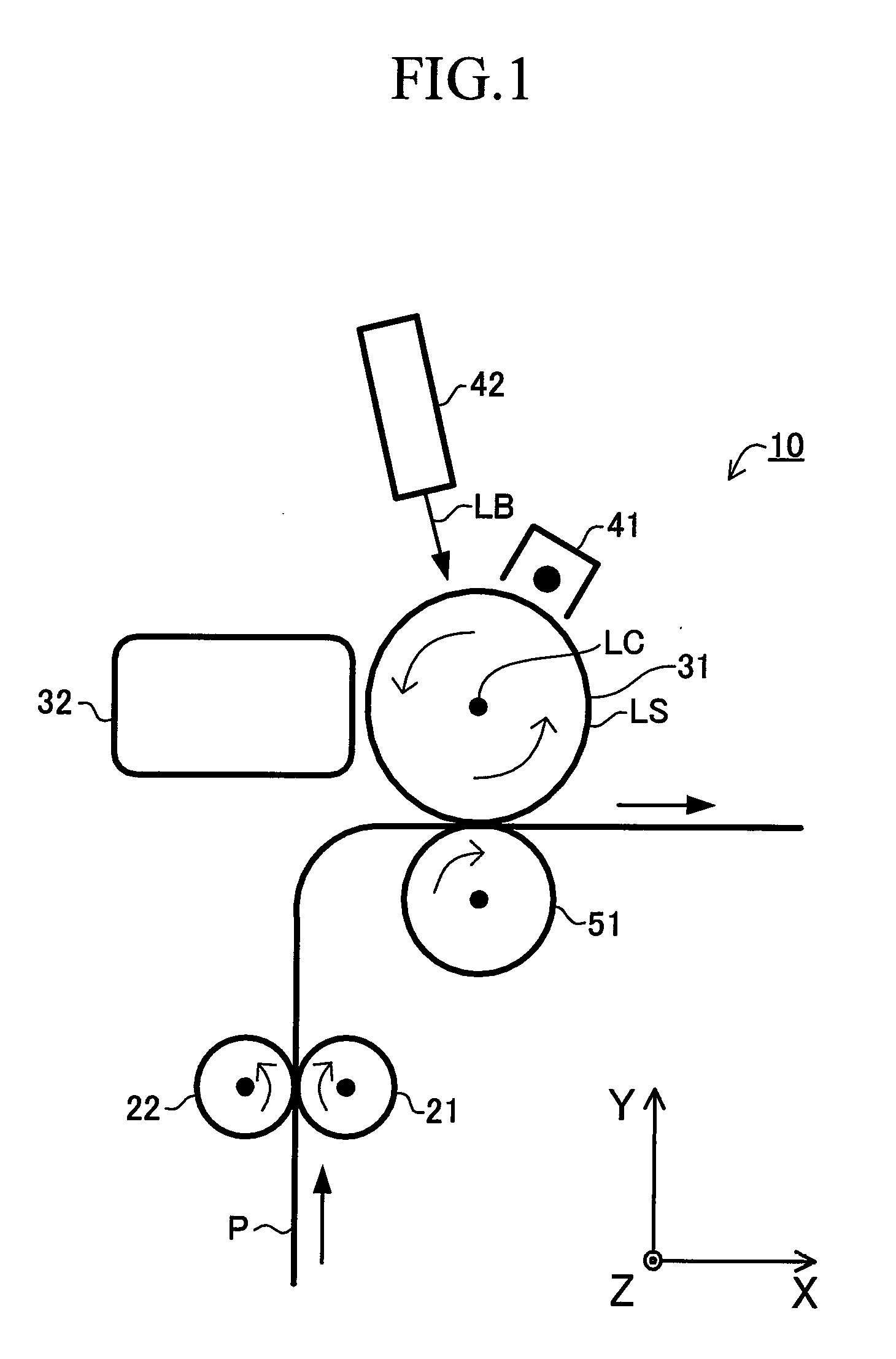
[0046]An image forming apparatus including a developer supply apparatus according to an embodiment of the present invention will next be described with reference to the drawings. The image forming apparatus is a laser printer (image forming apparatus) 10 whose schematic side sectional view is shown in FIG. 1 and which is adapted to perform monochromatic printing.

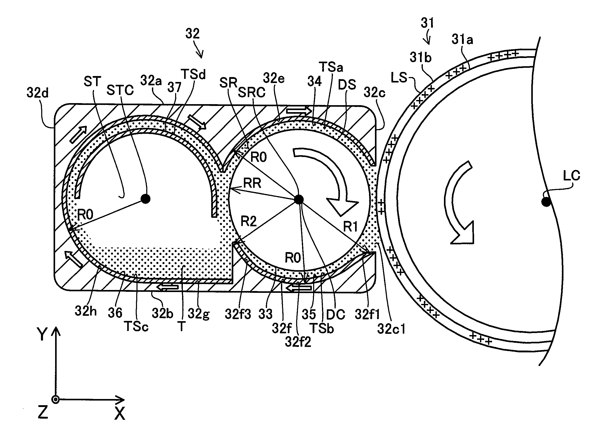
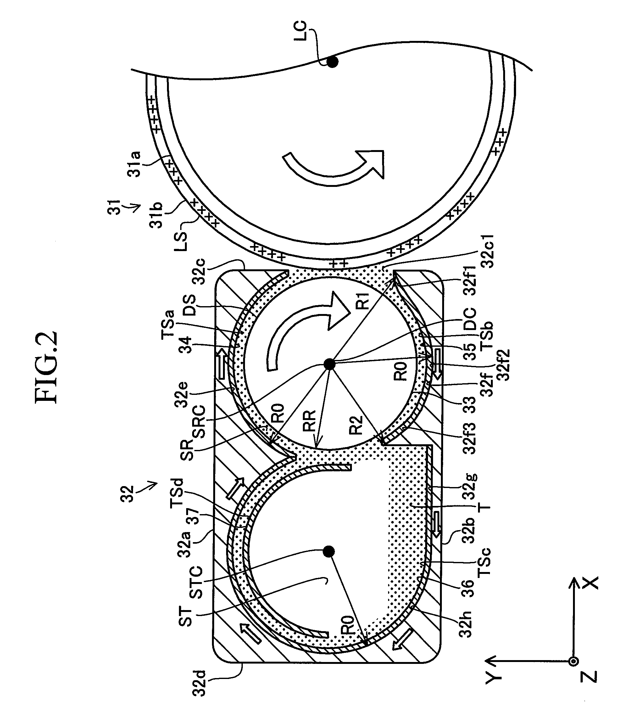
[0047]As shown in FIG. 1, the laser printer 10 includes a pair of resist rollers 21 and 22; a photoconductor drum 31, which serves as a latent image carrying body; a developer supply apparatus 32, which serves as developer supply means; a charger 41; a scanner unit 42; and a transfer roller 51. The photoconductor drum 31 and the developer supply apparatus 32 constitute a process unit.

[0048]The laser printer 10 accommodates paper P, which serves as a recording medium, in a stacked condition within an unillustrated paper feed tray. The laser printer 10 is configured such that the accommodated paper P is sent out s...


PUM


Abstract

An apparatus includes an upstream transport surface TSa which, while facing a circumferential surface DS of a developing roller 33, is disposed upstream of an area (developing area) in the vicinity of a latent image forming surface LS, and a downstream transport surface TSb which, while facing the circumferential surface, is disposed downstream of the developing area. The apparatus forms electric fields on the upstream and downstream transport surfaces for moving a charged developer T from an upstream side toward a downstream side. In the apparatus, the transport speed of developer on the upstream transport surface is higher than that on the downstream transport surface. As a result, there can be lowered a speed at which the developer which has not adhered to the circumferential surface and has reached a downstream end portion of the upstream transport surface flies out toward the vicinity of the developing area. Also, there can be avoided a problem in that the developer stagnates at an upstream end portion of the downstream transport surface with a resultant hindrance to collection of the developer.

Description

TECHNICAL FIELD[0001]The present invention relates to a developer supply apparatus in which a developer is transported along the circumferential surface of a developer carrying body by means of electric fields and thus adheres to the circumferential surface, and which supplies the adhering developer to a latent image forming surface on which an electrostatic latent image is formed, as well as to an image forming apparatus which includes the developer supply apparatus.BACKGROUND ART[0002]A conventionally known image forming apparatus is configured as follows. A developer is supplied in such a manner that the developer is uniformly distributed on the circumferential surface (developer carrying surface) of a rotatively driven developing roller without involvement of contact between the developing roller and developer supply members, such as a supply roller. A portion of the developer adhering to the circumferential surface of the developing roller adheres to the circumferential surface...

Claims


Application Information

Patent Timeline
Patent Type & Authority Applications(United States)
IPC IPC(8): G03G15/08
CPCG03G15/0806
Inventor NISHIWAKI, KENJIRO
Owner BROTHER KOGYO KK
Why Eureka
Try Eureka