
Spring roller blind system

a roller blind and spring technology, applied in the direction of door/window protective devices, building components, construction, etc., can solve the problems of time-consuming and inconvenient adjustment of the height adjusting module and the winding modul

Active Publication Date: 2021-06-01
LAI YUNG CHING
View PDF7 Cites 4 Cited by
  • Summary
  • Abstract
  • Description
  • Claims
  • Application Information

AI Technical Summary

Benefits of technology

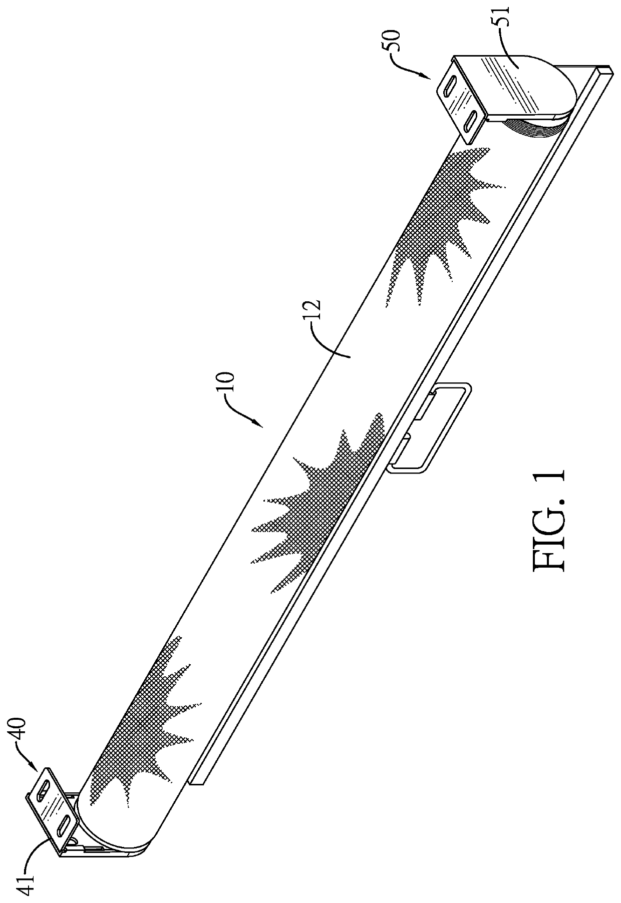
[0008]The main objective of the invention is to provide a spring roller blind system that may solve the problem that the adjustments of the height adjusting module and the winding module by the main adjusting devices are inconvenient and time-consuming.
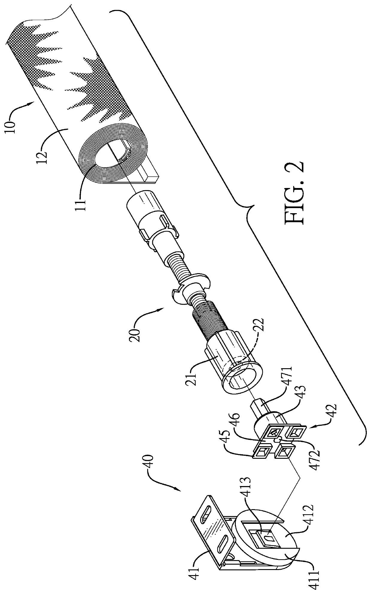
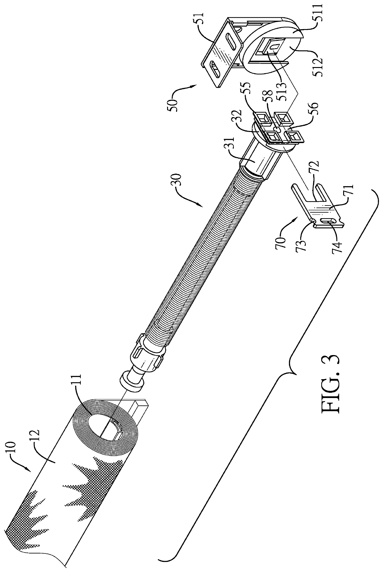
[0019]Accordingly, a rotating axis of the auxiliary adjusting element and a rotating axis of the first main adjusting element are the same. The number of turns of the auxiliary adjusting element is the same as the number of turns of the first main adjusting element. The auxiliary adjusting element is easy in operation. The adjustment of the height adjusting module is convenient and saves time. By the same token, the adjustment of the winding module is convenient and saves time. Furthermore, the fixing element can position the second main adjusting element after adjustment for increasing the adjusting convenience of the winding module.

Problems solved by technology

The adjustments of the height adjusting module and the winding module are inconvenient and time-consuming.

Method used


Image

  • Spring roller blind system
  • Spring roller blind system
  • Spring roller blind system

Examples


Embodiment Construction

[0035]In the following detailed description, for purposes of explanation and not limitation, an example embodiment disclosing specific details is set forth in order to provide a thorough understanding of the inventive principles and concepts. However, it will be apparent to one having ordinary skill in the art having the benefit of the present disclosure that other embodiments according to the present teachings that depart from the specific details disclosed herein remain within the scope of the appended claims. Moreover, descriptions of well-known apparatuses and methods may be omitted so as to not obscure the description of the preferred embodiment. Such methods and apparatuses are clearly within the scope of the present disclosure.

[0036]Relative terms may be used to describe the various elements' relationships to one another, as illustrated in the accompanying drawings. These relative terms are intended to encompass different orientations of the device and / or elements in addition...


PUM


Abstract

A spring roller blind system is provided that has a roller blind module, a height adjusting module, a winding module, a first main adjusting device disposed on the height adjusting module, a second main adjusting device disposed on the winding module, an auxiliary adjusting element, and a fixing element. The height adjusting module and the winding module are respectively disposed on two ends of the roller blind module. The auxiliary adjusting element is selectively and detachably disposed on a first main adjusting element of the first main adjusting device or a second main adjusting element of the second main adjusting device for adjusting the height adjusting module or the winding module. The fixing element is selectively inserted into a fixing recess of the winding module for positioning the second main adjusting element.

Description

BACKGROUND OF THE INVENTION1. Field of the Invention[0001]The present invention relates to a spring roller blind system, and more particularly a spring roller blind system that may be convenient in adjustment2. Description of Related Art[0002]A conventional spring roller blind system has a roller blind module, a height adjusting module, a winding module, and two main adjusting devices. The roller blind module has a roller tube and a blind. The roller tube has a first end and a second end opposite to the first end of the roller blind. The blind is retractably wound on the roller tube. The height adjusting module is inserted into the first end of the roller tube and has a height-adjusting head inserted into the first end of the roller tube. The winding module is inserted into the second end of the roller tube and has a winding-adjusting head. The two main adjusting devices are respectively inserted into the height-adjusting head of the height adjusting module and the winding-adjusting...

Claims


Application Information

Patent Timeline
Patent Type & Authority Patents(United States)
IPC IPC(8): E06B9/42E06B9/60
CPCE06B9/42E06B9/60E06B9/50
Inventor LAI, YUNG-CHING
Owner LAI YUNG CHING
Learn More