Light emitting module

a technology of light-emitting modules and leds, which is applied in the direction of fixed installation, light sources, lighting and heating apparatus, etc., can solve the problems of large number of leds at the bottom of mixing chambers, low efficiency, and inability to emit light from the sides, so as to achieve efficient and uniform illumination

Active Publication Date: 2021-06-08
SIGNIFY HLDG BV
View PDF18 Cites 0 Cited by
  • Summary
  • Abstract
  • Description
  • Claims
  • Application Information

AI Technical Summary

Benefits of technology

[0007]It is an object of the present invention to provide a light emitting module that provides relatively efficient and uniform illumination from both the top surface and from the side surface.

Problems solved by technology

However, LEDs are point sources and hence there is a problem of producing LED based light emitting modules providing uniform illumination.
Placing LEDs at the bottom surface can lead to visibility of individual LEDs, which provides a so-called undesired spottiness appearance.
Furthermore placing large number of LEDs at the bottom of a mixing chamber is costly.
The known device has as a disadvantage that light is not emitted from the sides.

Method used


Image

  • Light emitting module
  • Light emitting module
  • Light emitting module

Examples


Embodiment Construction

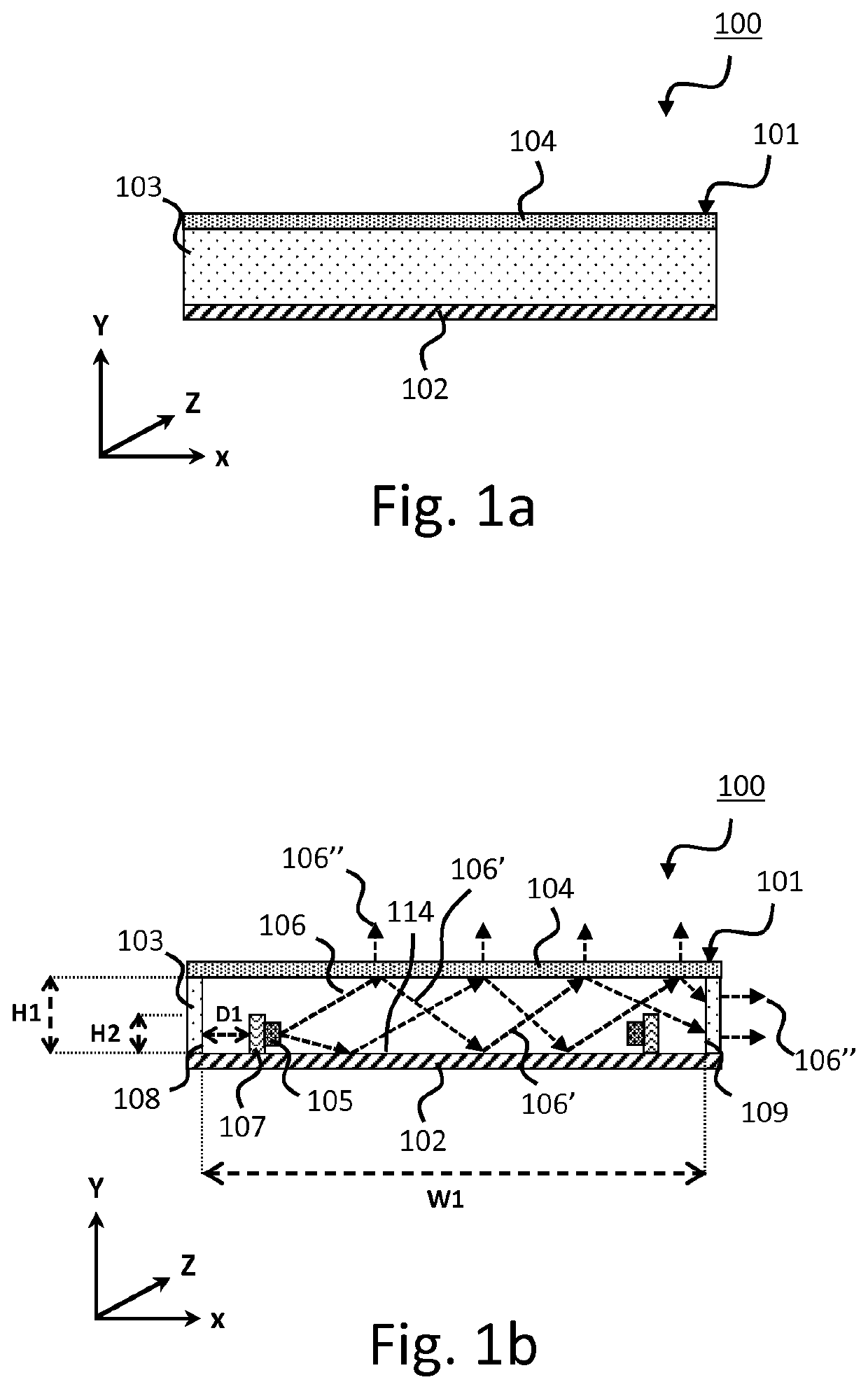
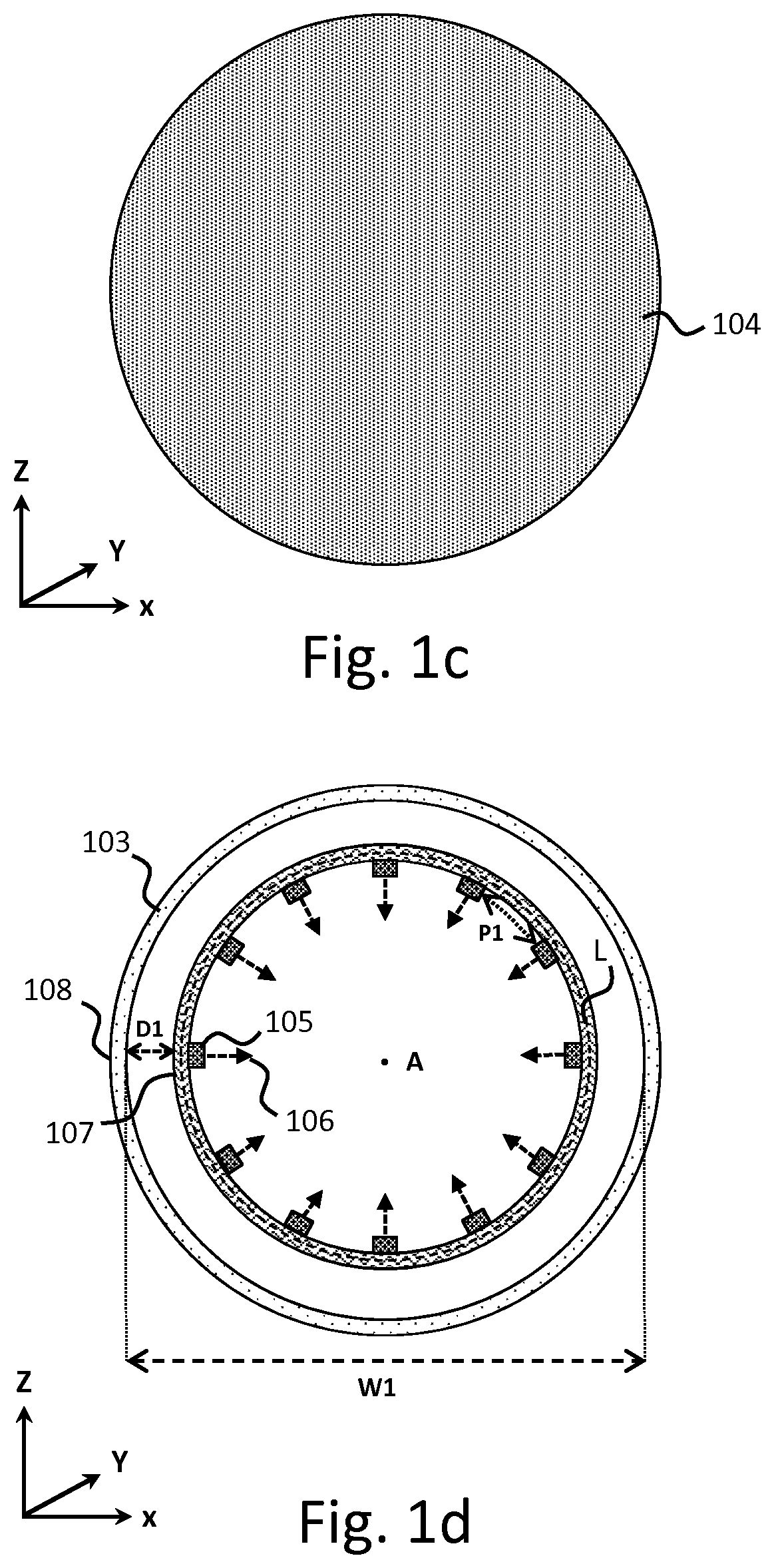
[0045]FIG. 1a-1d schematically depicts a light emitting module according (100) to an embodiment of the present invention. FIG. 1a schematically depicts a side-view of the lighting emitting module (100) along the length direction in the XY plane according to an embodiment of the present invention. FIG. 1b schematically depicts a cross-section of the lighting emitting module (100) along the length direction in the XY plane according to an embodiment of the present invention. FIG. 1c schematically depicts a top-view of the lighting emitting module (100) along the length direction in the XZ plane according to an embodiment of the present invention. FIG. 1d schematically depicts a cross-section of the lighting emitting module (100) along the length direction in the XZ plane according to an embodiment of the present invention.

[0046]As depicted in FIG. 1a-1d, the light emitting module (100) comprises a mixing chamber (101). The mixing chamber (101) comprises a base (102), at least one side...


PUM

PropertyMeasurementUnit
reflectivityaaaaaaaaaa
aspect ratioaaaaaaaaaa
reflectivityaaaaaaaaaa

Abstract

The invention provides a light emitting module (100) which comprises a light mixing chamber (101). The light mixing chamber comprises a base (102), at least one partly light transmissive side wall (103), an at least partly light transmissive-semi-reflective light exit window (104), a carrier (107), and at least one light emitting diode (105). The base (102) has a reflective inner surface (114). The at least one partly light transmissive side wall (103) extends from the base (102) towards the at least partly light transmissive, semi-reflective light exit window (104) which is arranged opposite to the base (102). The carrier (107) carries at least one light emitting diode (105) and is positioned at a distance (D1) from a nearest portion (108) of the at least one partly light transmissive side wall (103). The at least one light emitting diode (105) is arranged to emit source light (106) in a main direction different from 90 degrees with respect to the semi-reflective light exit window (104) and in the main direction away from the nearest portion (108) of the at least one partly light transmissive side wall (103) to enable subsequent mixing of the source light (106) within the mixing chamber (101) to generate mixed light (106′). The semi-reflective light exit window (104) and the at least one partly light transmissive side wall (103) are arranged to couple out source light (106) and mixed light (106′) as emitted light (106″). The mixing chamber has an inner mixing chamber width (W1) in the direction along the base (102) between the nearest portion (108) of the at least one partly light transmissive side wall (103) and an opposite portion (109) of the at least one partly light transmissive side wall (103) which is positioned opposite to the nearest portion (108) of the at least one partly light transmissive side wall (103). An inner mixing chamber height (H1) spaces the base (102) and the semi-reflective light exit window (104). The inner mixing chamber width (W1) and the inner mixing chamber height (H1) have an aspect ratio in the range of 4 to 15. The semi-reflective light exit window (104) has a reflectivity in the range from 30 to 80% for source light (106) and mixed light (106′). The distance (D1) from the at least one light emitting diode (105) to the nearest portion (108) of the at least one partly light transmissive side wall (103) is in the range from 5 to 30% of the inner mixing chamber width (W1).

Description

CROSS-REFERENCE TO PRIOR APPLICATIONS[0001]This application is the U.S. National Phase application under 35 U.S.C. § 371 of International Application No. PCT / EP2018 / 069412, filed on Jul. 17, 2018, which claims the benefit of European Patent Application No. 17182652.2, filed on Jul. 21, 2017. These applications are hereby incorporated by reference herein.FIELD OF THE INVENTION[0002]The present invention relates to a light emitting module which comprises a light mixing chamber and least one light emitting diode. The present invention further relates to a lamp and a luminaire comprising such a light emitting module. The present invention further relates to a lighting system comprising at least two light emitting modules and / or at least two lamps or luminaires.BACKGROUND OF THE INVENTION[0003]The field of light emitting modules includes a large variety of different light emitting modules regarding use of light sources, construction, optical characteristics, etc. These light emitting mod...

Claims


Application Information

Patent Timeline
Patent Type & Authority Patents(United States)
IPC IPC(8): F21K9/62F21K9/68F21Y103/33F21Y115/10F21Y105/00
CPCF21K9/62F21K9/68F21Y2103/33F21Y2105/00F21Y2115/10F21S8/06F21K9/23
Inventor VAN BOMMEL, TIESPET, ROBERT JACOBVAN EEUWIJK, ALEXANDER HENRICUS WALTERUS
Owner SIGNIFY HLDG BV
Why Eureka
Try Eureka