Photovoltaic system for efficient solar radiation collection and solar panel incorporating same

a photovoltaic system and solar panel technology, applied in photovoltaics, electrical devices, semiconductor devices, etc., can solve the problems of reducing affecting the efficiency of light management, so as to achieve high quality optical focus of light, small angular acceptance, and thin form factor

Inactive Publication Date: 2012-11-29
SHARP KK
View PDF5 Cites 5 Cited by
  • Summary
  • Abstract
  • Description
  • Claims
  • Application Information

AI Technical Summary

Benefits of technology

[0004]As discussed above the most commonly used concentration optics for a concentrated photovoltaic system consists of a primary Fresnel lens concentrator with a small angular acceptance for the collection and focusing of direct sunlight. This concentration lens has the benefits of providing a high quality optical focus of the light and a very thin form factor as well as easily being manufactured in different shapes like cylindrical or circular. However due to the Fresnel lens having only one optically smooth major surface and a second faceted optical surface it is difficult to apply anti reflection coatings to both surfaces which reduces the efficiency of light management. The secondary concentrator commonly used has the shape of a frustum in the circular case and a clipped triangular prism in the cylindrical case. More complex forms like a compound parabolic concentrator are used as well. This secondary concentrator is disposed with the smaller of the two major parallel surfaces on the photovoltaic cell and the larger of the two major parallel surfaces opens towards the Fresnel cell. The Fresnel lens is directing the collected solar radiation towards the secondary concentrator which is designed in such a way as to mix and guide the light towards the photovoltaic cell and provide efficient and uniform illumination of the photovoltaic cell. Although this secondary concentrator is usually glued to the photovoltaic cell, using an index matching glue with a refractive index between the refractive index of the dielectric material of the secondary concentrator and the semiconductor material of the photovoltaic cell, reflection losses occur at these transitional surfaces.
[0005]The current invention relates to an optical component in a concentrated photovoltaic system and the management of light reflected back out of the system from the transitional surfaces between the secondary concentrator and the photovoltaic cell, and to a concentrated photovoltaic system including such an optical component. In particular the current invention relates to a secondary light mixing concentrator preferably with the larger of the two parallel primary optical surfaces which faces the primary concentrating Fresnel lens being provided with a non-planar, preferably corrugated surface structure. The non-planar, and preferably corrugated surface structure is designed in such a way that it reflects light otherwise being lost out of the system due to reflections below at the transitional surfaces between the secondary light mixing concentrator and the photovoltaic cell back towards the photovoltaic cell. This allows the optical efficiency of the concentrated photovoltaic system to be improved. In addition the corrugated surface structure allows improving management of the light from the periphery of the Fresnel lens and therefore it can improve concentration ratios as well. Furthermore the corrugated surface structure provides additional light mixing which improves uniform illumination of the photovoltaic cell and hence increases reliability and durability of the photovoltaic cell. As a further benefit the light management capacity of the corrugated surface structure can be extended to improve the usage of the diffuse part of the solar radiation which generally is a shortcoming of concentrated photovoltaic systems. Efficient use of the diffuse part of the solar radiation will allow concentrated photovoltaic systems quicker and more widespread market penetration as it enables their commercial use in more areas of the planet where a large part of the solar radiation is made up of diffuse light.
[0022]In still another aspect, the system further includes a receptacle formed by a set of side walls and bottom plate in which the photovoltaic cell and secondary light mixing concentrator are located, and shaped mirror structures on the bottom plate to more efficiently direct diffuse solar radiation to the photovoltaic cell.

Problems solved by technology

However due to the Fresnel lens having only one optically smooth major surface and a second faceted optical surface it is difficult to apply anti reflection coatings to both surfaces which reduces the efficiency of light management.
Although this secondary concentrator is usually glued to the photovoltaic cell, using an index matching glue with a refractive index between the refractive index of the dielectric material of the secondary concentrator and the semiconductor material of the photovoltaic cell, reflection losses occur at these transitional surfaces.

Method used


Image

  • Photovoltaic system for efficient solar radiation collection and solar panel incorporating same
  • Photovoltaic system for efficient solar radiation collection and solar panel incorporating same
  • Photovoltaic system for efficient solar radiation collection and solar panel incorporating same

Examples


first embodiment

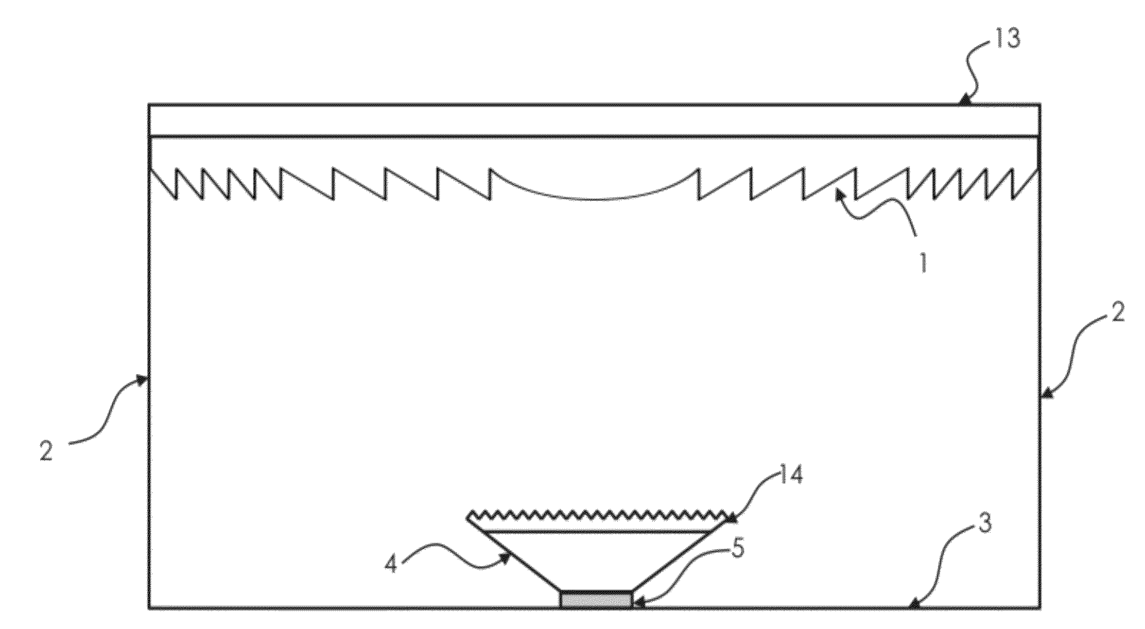
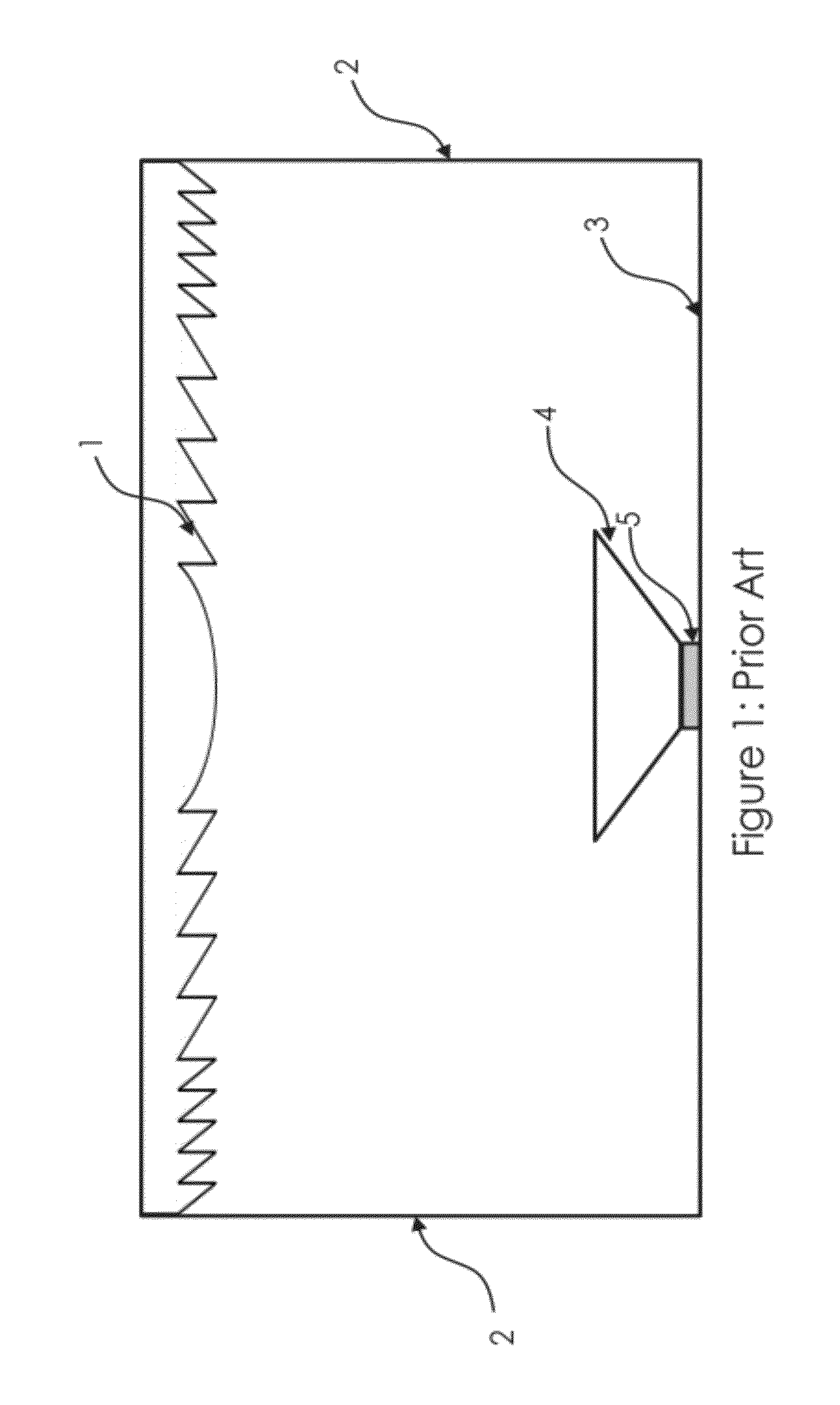
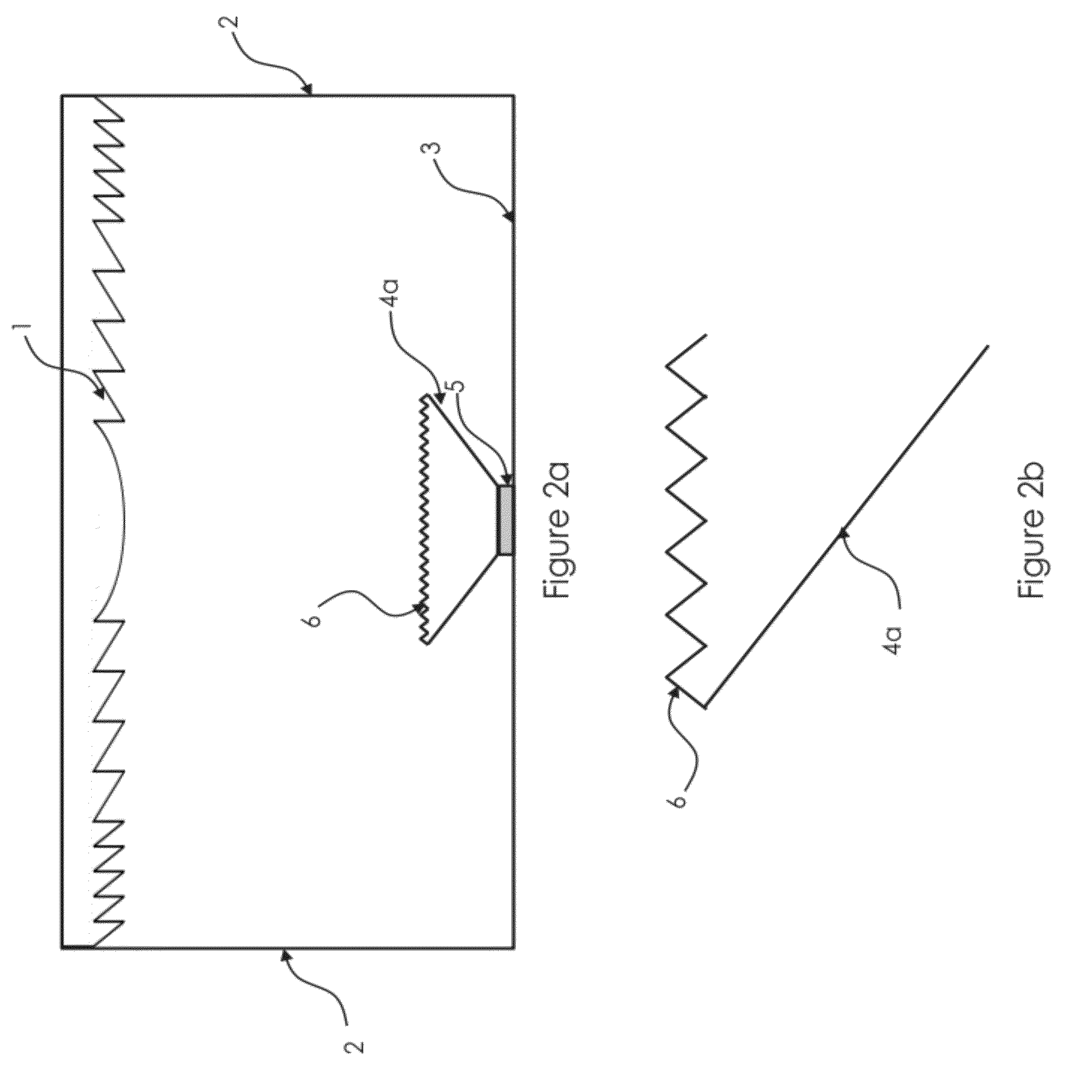
[0059]FIG. 2a shows a schematic cross sectional view of a primary embodiment of a concentrated photovoltaic system in accordance with the current invention; FIG. 2b provides a close up view of part of the current invention; and FIG. 2c provides a partial perspective view of the embodiment of FIG. 2a. The depicted concentrated photovoltaic system uses a Fresnel lens 1 as primary concentrator to collect the direct solar radiation over a relatively large area and then concentrate the light towards the photovoltaic cell 5 with a relatively small area. Before reaching the photovoltaic cell 5 the light is concentrated and mixed by the secondary light mixing concentrator 4a which is positioned on top of the photovoltaic cell 5 and in optical contact with the photovoltaic cell 5. The secondary light mixing concentrator 4a differs from the secondary light mixing concentrator 4 (FIG. 1) in the prior art at least in part because of prismatic surface structures 6 on the larger primary surface o...

second embodiment

[0060]FIG. 3 shows a schematic cross section of the current invention which differs from the primary embodiment in so far as it does not use a Fresnel lens 1 for the primary concentration optics but instead has another primary light concentrating optic 7. The depiction of the primary light concentrating optic 7 in FIG. 3 is general and the current invention covers any primary light concentrating optic 7 using refraction, reflection, total internal reflection or a mixture of these processes. Furthermore the current invention is not limited to a primary light concentrating optic 7 consisting only of a single element, but an assembly of a number of elements constituting the primary light concentrating optic 7 is also within the scope of the current invention.

[0061]The depiction of embodiments of the current invention focuses on linear arrangements of the Fresnel lens 1; however embodiments covered by the current invention are not limited to that. In FIG. 4a a three dimensional view of ...


PUM


Abstract

A concentrated photovoltaic system includes a photovoltaic cell; a primary light concentrating optic; and a secondary light mixing concentrator. The primary light concentrating optic is arranged to collect solar radiation and concentrate the collected solar radiation towards the secondary light mixing concentrator. The secondary light mixing concentrator is arranged to concentrate the concentrated solar radiation from the primary light concentrating optic towards the photovoltaic cell. The secondary light mixing concentrator includes a dielectric member having first and second primary surfaces, with the second primary surface being in optical contact with the photovoltaic cell and the first primary surface facing the primary light concentrating optic. The first primary surface has a non-planar surface structure configured to redirect light which is reflected at transitional surfaces between the secondary light mixing concentrator and the photovoltaic cell back towards the photovoltaic cell.

Description

TECHNICAL FIELD[0001]The present invention relates to a photovoltaic system for the collection and concentration of solar radiation onto a photovoltaic cell for electrical power generation. More particularly the present invention relates to a photovoltaic system with a primary optical element used to concentrate direct solar radiation onto a secondary structured optical element which condenses the collected radiation onto a photovoltaic cell.BACKGROUND ART[0002]Concentrated photovoltaic systems are optical systems which collect the sun's light over a relatively large area and concentrate this light onto a photovoltaic cell of a much smaller surface area commonly consisting of a semiconductor material like silicon, gallium-arsenide or cadmium-telluride. The concentrated sunlight is then converted into electric energy with a certain efficiency by the photovoltaic cell. This approach is very favorable because it allows the price of electricity generated through photovoltaic energy conv...

Claims


Application Information

Patent Timeline
Patent Type & Authority Applications(United States)
IPC IPC(8): H01L31/052H01L31/0232
CPCH01L31/0543Y02E10/52
Inventor ROHRMOSER, STEFANMITCHELL, SARAH ANNEMONTGOMERY, DAVID JAMESSUCKLING, JAMES ROWLAND
Owner SHARP KK
Why Eureka
Try Eureka