Systems and methods for illuminating a platen in a print scanner

a platen and print scanner technology, applied in the field of biometric imaging technology, can solve problems such as non-uniform illumination source arrays, and achieve the effects of increasing the dynamic range of grey scale shading, and reducing the number of plates

Inactive Publication Date: 2006-08-03
CROSS MATCH TECH
View PDF168 Cites 9 Cited by
  • Summary
  • Abstract
  • Description
  • Claims
  • Application Information

AI Technical Summary

Benefits of technology

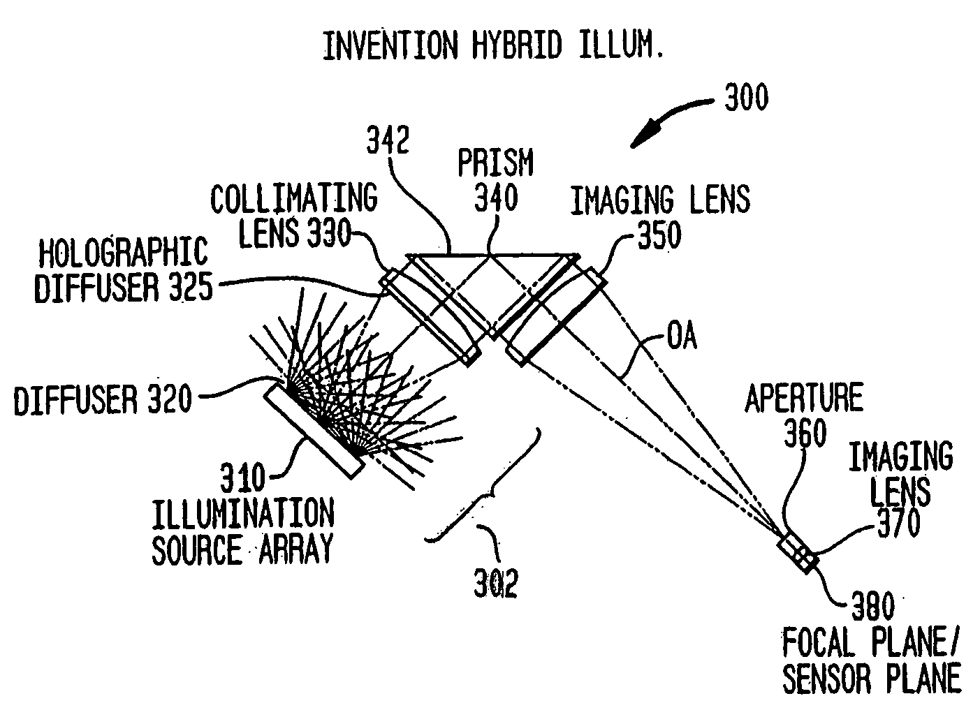
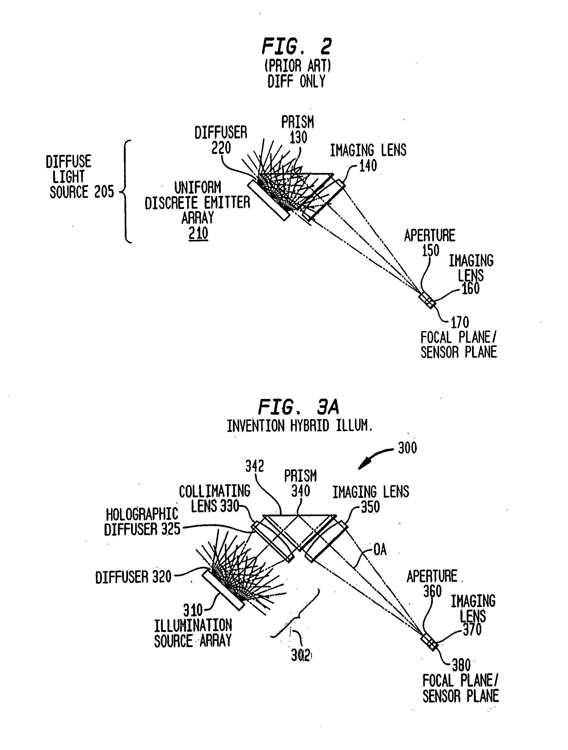
[0013] According to one embodiment of the present invention, a hybrid illumination system provides illumination to a platen in a print scanner. The hybrid illumination system uses both diffusion and collimation to efficiently provide a flat, uniform illumination at a platen. An illumination source array emits light from a plurality of discrete light sources. One or more diffusers are disposed between the illumination source array and a collimating lens. At least part of the light emitted from the plurality of discrete light sources passes through at least one diffuser and then through a collimating lens. Each diffuser serves to randomize light so that a flat, uniform illumination is obtained at the platen. The individual cones of light initially emitted from the discrete sources are no longer visible. The collimating lens increases the efficiency of the illumination system and reduces the power requirements of the illumination source array. Fewer light sources are needed. This efficiency is especially advantageous in a telecentric optical system of a print scanner.
[0019] According to a further feature of the present invention, the intensity of each source of an illumination source array can be independently controlled relative to other sources. For example, each source can be a light emitting diode which is individually current controlled to correct for or minimize drift and to ensure a flat, uniform illumination is provided to a platen.
[0020] According to a further feature of the present invention, the illumination source array is divided into zones. In one embodiment, a plurality of sources are divided into at least three groups in at least three respective zones. The intensity of each group of sources is independently controlled relative to other groups such that a flat, uniform illumination is provided to the platen. Use of such zones simplifies control while still retaining sufficient flexibility to adjust the relative intensity of the light source groups to ensure flat, uniform illumination is provided to a platen.
[0021] According to a further feature of the present invention, an illumination source array comprises a plurality of sources that emit blue / green light. In one preferred example, the blue / green light is equal to or approximately equal to 510 nm. A method includes the steps of emitting blue / green light from a plurality of discrete sources, and illuminating a platen with at least part of the emitted blue / green light. Compared to conventional red light operating at 650 nm, the inventors found that blue / green light increases the dynamic range of grey scale shading in an image of a print of a finger or palm detected with a print scanner.
[0022] According to another embodiment, a method provides flat, uniform illumination efficiently to a platen. The method includes the steps of emitting light from a plurality of discrete sources, randomizing the emitted light to obtain diffuse light, collimating at least part of the diffuse light, and illuminating the platen such that an image of a print of a finger or palm placed on the platen can be obtained. The randomizing step can include passing the emitted light through at least one diffuser or through a light wedge. In one example, the emitting step includes emitting blue / green light.
[0024] According to a further embodiment, a system for providing flat, uniform illumination efficiently to a platen includes means for emitting light, means for randomizing at least part of the emitted light to obtain diffuse light, and means for collimating at least part of the diffuse light. In this way, a portion of the diffuse light is collimated and falls on the platen as collimated light, while remaining diffuse light falls on the platen as diffuse light. The platen is illuminated with this collimated, diffuse light such that a high contrast image of a print of a finger or palm placed on the platen is obtained.

Problems solved by technology

The third technique involves use of a non-uniform illumination source array and use of independent and / or zone controlled light sources.

Method used


Image

  • Systems and methods for illuminating a platen in a print scanner
  • Systems and methods for illuminating a platen in a print scanner
  • Systems and methods for illuminating a platen in a print scanner

Examples


Embodiment Construction

Table of Contents

1. Overview

2. Terminology

3. Hybrid Collimated / Diffuse Illumination System

4. Illumination System Having a Light Wedge

5. Non-Uniform Illumination Source and Control

6. Blue / Green Illumination

7. Conclusion

[0040] While the present invention is described herein with reference to illustrative embodiments for particular applications, it should be understood that the invention is not limited thereto. Those skilled in the art with access to the teachings provided herein will recognize additional modifications, applications, and embodiments within the scope thereof and additional fields in which the present invention would be of significant utility.

1. Overview

[0041] The present invention provides illumination for any type of print scanner, including, but not limited to, any type of fingerprint and / or palm print scanner.

2. Terminology

[0042] To more clearly delineate the present invention, an effort is made throughout the specification to adhere to the follow...


PUM


Abstract

Systems and methods for illuminating a platen are provided. A hybrid illumination system uses both diffusion and collimation to efficiently provide a flat, uniform illumination at a platen. One or more diffusers are disposed between the illumination source array and a collimating lens. An illumination system is provided which uses diffused light to illuminate a platen in a print scanner. The illumination system has an illumination source array and a light wedge. The light wedge reflects light internally which makes the illumination even more diffuse. Sources are divided into at least a center region and a perimeter region. The density of sources provided in the perimeter region is greater than in the center region to correct for natural light falloff in the illumination system. Intensity control can be performed individually or in groups.

Description

BACKGROUND OF THE INVENTION [0001] 1. Field of the Invention [0002] The present invention pertains to biometric imaging technology, and in particular, to live scanning of fingerprints and / or palm prints. [0003] 2. Background Art [0004] Biometric imaging systems may include, but are not limited to, fingerprint imaging systems and palm print imaging systems. Such print imaging systems are also referred to as scanners or live scanners. Conventional live scanners use light to detect an image of a fingerprint and / or palm print. One or more fingers or palms are placed on a platen. An illumination source illuminates the underside of the platen. An image representative of valleys, ridges, or other characteristics of a fingerprint or a palm print is then detected by an image sensor, such as, a solid-state camera. [0005] The illumination source must have sufficient power so that a high quality image representative of a print is detected by the image sensor. Often the optical system employed i...

Claims


Application Information

Patent Timeline
Patent Type & Authority Applications(United States)
IPC IPC(8): G06K9/74A61B5/117G06T1/00G06V10/145H04N1/04
CPCG06K9/00046G06K9/2036G06V40/1324G06V10/145
Inventor ARNOLD, JOSEPH F.CARVER, JOHN F.FRANCIS, TRENT G.IRVING, RICHARD D.MCCLURG, GEORGE W.SCOTT, WALTER G.
Owner CROSS MATCH TECH
Why Eureka
Try Eureka