Remotely controllable aeronautical ordnance loitering

a technology of aeronautical ordnance and remote control, which is applied in the field of remote control of unmanned aerial vehicles (uavs), or drones, can solve the problems of losing the ability to personally control the trajectory of the sender and cannot alter the destination, so as to avoid collateral damage and provide propulsive lift

Active Publication Date: 2021-07-20
OVERWERX LTD
View PDF13 Cites 4 Cited by
  • Summary
  • Abstract
  • Description
  • Claims
  • Application Information

AI Technical Summary

Benefits of technology

[0006]In a first exemplary aspect of the invention, to achieve the above and other features and purposes, described herein is a method of delivering an explosive ordnance from a first altitude to a destination on or above a ground plane and avoiding collateral damage. The method includes providing an ordnance which includes a tubular shaped body having first and second opposing end portions and an explosive component positioned therein, a plurality of blades connected to the body at or near the first end portion blades for rotation about the body under powered operation to impart thrust and bring the ordnance to a first altitude above a target position, a motor positioned within the tubular shaped body, connected to selectively provide the powered operation to impart the thrust and thereby provide propulsive lift to the ordnance via the blade rotation, an imaging device mounted along the second end portion to generate frames of image data representative of a view of a ground plane while the ordnance is airborne, where the imaging device acquires infrared or visible light images, first receiver circuitry configured to receive radio frequency (rf) control signals and coupled to effect operation of other components of the ordnance in response to the received signals, rf video transmission circuitry coupled to receive the frames of image data and transmit rf signals including a stream of the image data. The method also includes providing a user controllable remote control device, positionable remote from the ordnance, which includes rf control circuitry that, responsive to user input, transmits control signals for a person to direct operation of the ordnance when flying and hovering, second receiver circuitry for receiving the stream of image data, and video processing circuitry that receives the image data from the rf circuitry and displays the image data on a screen where when the ordnance is airborne above a ground plane, the blades are positioned above the motor and are connected to the motor via a shaft for rotation about a central axis, and the imaging device is oriented to generate frames of image data representative of a view of a portion of the ground plane directly below the ordnance. The method further including initiating the powered operation to impart the propulsive lift to the ordnance, based on displayed frames of the image data acquired with the imaging unit positioned on the ordnance, sending one or more first control signals from the remote control device to navigate movement of the ordnance to an airborne position above the target position, sending one or more second control signals from the remote control device to cause the ordnance to descend toward the target position, and detonating the explosive component.

Problems solved by technology

All too often members of a military force carry missiles in the field and launch them to attack an enemy without being able to assure there will not be collateral damage to innocent people.
Moreover, regardless whether the explosive weapon is thrown or launched, once the projectile is air-borne, the person sending it loses ability to personally control the trajectory and cannot alter the destination.

Method used


Image

  • Remotely controllable aeronautical ordnance loitering
  • Remotely controllable aeronautical ordnance loitering
  • Remotely controllable aeronautical ordnance loitering

Examples


Embodiment Construction

[0064]Referring now to the drawings, there are shown exemplary embodiments of the method and structures according to the present invention.

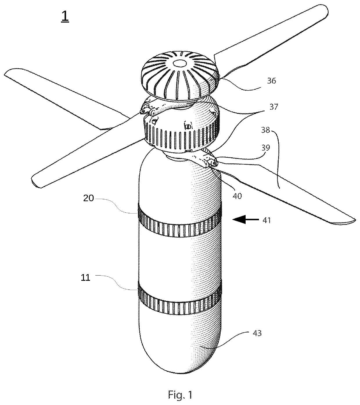
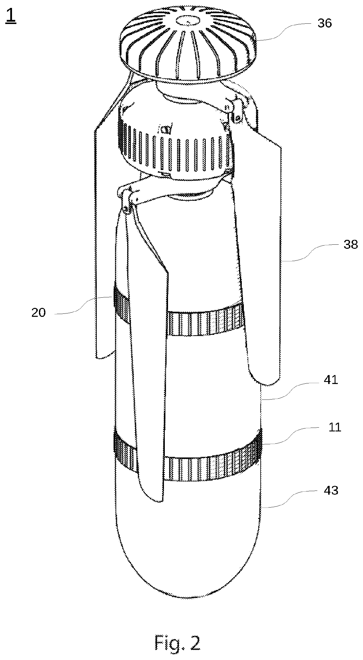
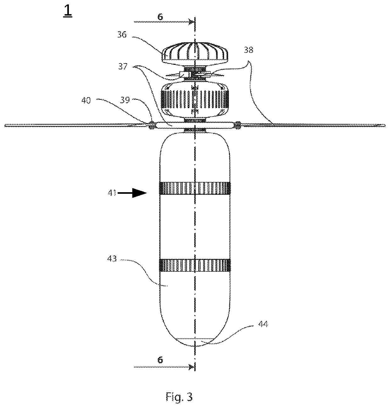
[0065]The illustrated embodiments of an ordnance 1 combine a payload with an unmanned flying device, referred to a coaxial drone, similar to that described in U.S. Pat. No. 10,093,417, assigned to Ascent AeroSystems, LLC. In other embodiments, the ordnance 1 may include other designs of an unmanned aerial vehicle (UAV) suitable for delivery to a target. In lieu of an explosive weapon carried and launched by an air-borne vehicle or the “dropping” of a payload carried by such a vehicle, the ordnance 1 includes an integrally formed UAV function for which flight is controllable in the field to reach a selected altitude and position above a target. Once positioned, the ordnance 1 can be controlled to drop in its entirety on the target.

[0066]FIG. 1 provides a view of the ordnance 1 in a powered-up configuration with propellers / rotary blades 38 extended...


PUM


Abstract

An ordnance for air-borne delivery to a target under remotely controlled in-flight navigation. In one embodiment, self-powered aerial ordnance includes upper and lower cases. A plurality of co-axial, deployable blades is powered by a motor positioned in the upper case. When deployed, the blades are rotatable about the upper case to impart thrust and bring the vehicle to a first altitude above a target position. An explosive material and a camera are positioned in a lower case which is attached to the upper case. The camera generates a view along the ground plane and above the target when the ordinance is in flight. When the vehicle is deployed it is remotely controllable to deliver the vehicle to the target to detonate the explosive at the target. The ordnance may drop directly on a target as a bomb does.

Description

PRIORITY AND RELATED APPLICATIONS[0001]This application claims priority to U.S. Provisional Patent Application Ser. No. 62 / 568,518, “Remotely Controllable Aeronautical Ordnance”, filed 5 Oct. 2017 and claims priority to U.S. Provisional Patent Application Ser. No. 62 / 726,976, 6Remotely Controllable Aeronautical Ordnance Loitering”, filed 4 Sep. 2018, and for which the disclosure of each is now incorporated herein by reference. This application is related to U.S. Pat. No. 10,093,417, filed 10 Nov. 2015, NUnmanned Flying Device”, which is incorporated herein by reference.FIELD OF THE INVENTION[0002]The invention relates to a remotely controlled unmanned aerial vehicle (UAV), or drone and, more particularly, one embodiment of an ordnance comprises a vehicle and an explosive component for delivery to a target.BACKGROUND[0003]All too often members of a military force carry missiles in the field and launch them to attack an enemy without being able to assure there will not be collateral d...

Claims


Application Information

Patent Timeline
Patent Type & Authority Patents(United States)
IPC IPC(8): F42B15/01G05D1/00F42B10/38G06K9/00F42C13/04F42B12/02F42B15/10H04N7/18F42C1/00
CPCF42B15/01F42B10/38F42B12/02F42B15/10F42C1/00F42C13/047G05D1/0022G05D1/0038G06K9/0063H04N7/185F42B12/42F42B12/365F42B12/46F42B12/50F42B25/00F42B15/08F42B10/62F42B10/14F42C13/04F42B12/20G05D1/12
Inventor HILL, JEFFREY
Owner OVERWERX LTD
Why Eureka
Try Eureka