Heat exchanger header with stiffening element

a technology of heat exchanger and header, which is applied in the direction of reinforcing means, corrosion prevention, stationary conduit assemblies, etc., can solve the problems of header bending or bending, leakage of one of the heat exchange fluid, etc., and achieve the effect of minimizing a bending or bending header

Active Publication Date: 2021-07-27
HANON SYST
View PDF59 Cites 1 Cited by
  • Summary
  • Abstract
  • Description
  • Claims
  • Application Information

AI Technical Summary

Benefits of technology

[0006]Compatible and attuned with the present invention, a stiffening element for a heat exchanger that reinforces a header of the heat exchanger for minimizing a flexing or bending of the header has been surprisingly discovered.

Problems solved by technology

The presence of a bending moment within one of the headers can lead to a bending or flexing of the header.
The increased stress can potentially lead to failure at this junction, thereby presenting the possibility of leakage of one of the heat exchanging fluids from the heat exchanger tube.

Method used


Image

  • Heat exchanger header with stiffening element
  • Heat exchanger header with stiffening element
  • Heat exchanger header with stiffening element

Examples


Embodiment Construction

[0024]The following detailed description and appended drawings describe and illustrate various embodiments of the invention. The description and drawings serve to enable one skilled in the art to make and use the invention, and are not intended to limit the scope of the invention in any manner. In respect of the methods disclosed, the steps presented are exemplary in nature, and thus, the order of the steps is not necessary or critical.

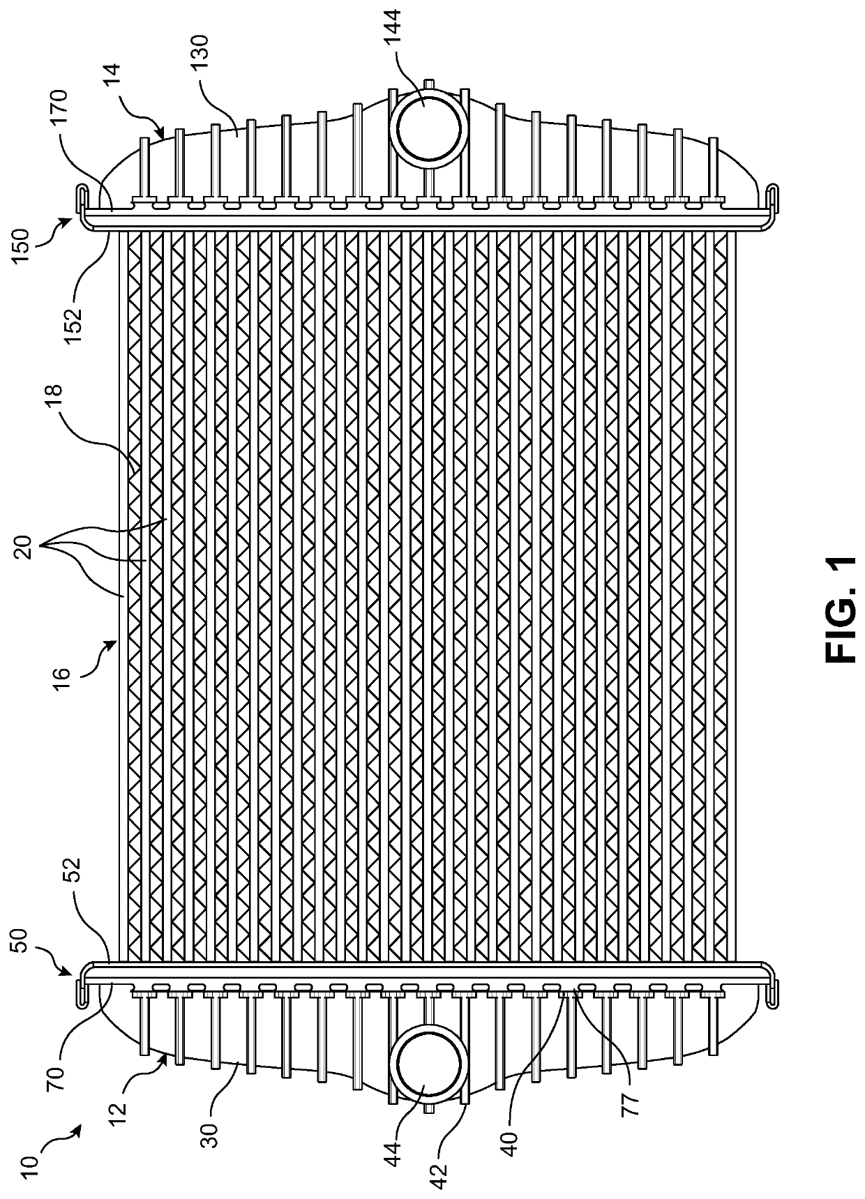
[0025]FIG. 1 illustrates a heat exchanger 10 according to an embodiment of the invention. The heat exchanger 10 may be used for any heat exchanging application such as forming an evaporator or a condenser of an air conditioning system, a radiator of a cooling system, or a charge air-cooler of a turbocharger system, as non-limiting examples. The heat exchanger 10 may be configured to pass any type of fluid therethrough, including a refrigerant or a coolant, as non-limiting examples. The fluid passed by the heat exchanger 10 may be configured for exchan...


PUM


Abstract

A header tank for a heat exchanger comprises a casing having a hollow interior and a header assembly coupled to the casing. The header assembly comprises a header having a plurality of tube openings formed therein and a stiffening element coupled to the header. The stiffening element includes a stiffening wall extending from a first longitudinal side of the header to an opposing second longitudinal side of the header to provide additional bending stiffness to the header assembly.

Description

FIELD OF THE INVENTION[0001]The invention relates to a heat exchanger, and more specifically to a stiffening element configured for increasing a bending stiffness of a header tank of the heat exchanger.BACKGROUND OF THE INVENTION[0002]Heat exchangers typically include a centralized plurality of heat exchanger tubes or passageways connected at each respective end thereof to one of an inlet tank and an outlet tank. The plurality of heat exchanger tubes forms a heat exchanger core of the heat exchanger for transferring heat energy between two different heat exchanging fluids. The inlet tank and the outlet tank each typically include a surface that acts as a header having tube openings for receiving end portions of the heat exchanger tubes therein. The header of each of the tanks is then coupled to a casing of the tanks that aids in distributing or collecting a fluid flowing through the heat exchanger tubes.[0003]It is not uncommon for slight temperature variations to exist at different...

Claims


Application Information

Patent Timeline
Patent Type & Authority Patents(United States)
IPC IPC(8): F28F9/00F28F19/00F28F9/02
CPCF28F19/00F28F9/0226F28F2009/0297F28F2225/08F28D1/05366F28D2021/0091F28F9/0214F28F2009/029
Inventor DZIUBINSCHI, OREST ALEXANDRUHANSON, KYLESICKS, BRENNANDURAISWAMY, DURAI
Owner HANON SYST
Why Eureka
Try Eureka