
Fatigue-resistant emergency release device for rail transit vehicle coupler

a technology for rail transit vehicles and emergency release bolts, which is applied in the direction of railway coupling accessories, buffers, draw-gears, etc., can solve the problems of reducing the fatigue strength of the bolts, breaking or shearing of the emergency release bolts, etc., and achieves the effect of minimizing the flexing of the release bolts

Active Publication Date: 2010-08-03
WABTEC HLDG CORP
View PDF6 Cites 4 Cited by
  • Summary
  • Abstract
  • Description
  • Claims
  • Application Information

AI Technical Summary

Benefits of technology

[0011]It is an object of this invention to provide a fatigue-resistant emergency release device for rail transit vehicle coupler assemblies. Specifically, the release device is provided with enhanced fatigue life performance for emergency release bolts by eliminating bending forces exerted on the emergency release bolts.
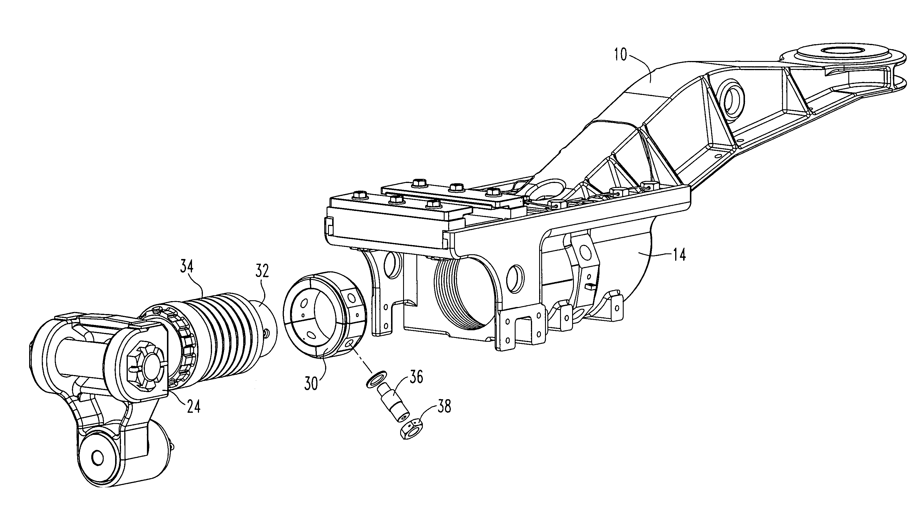
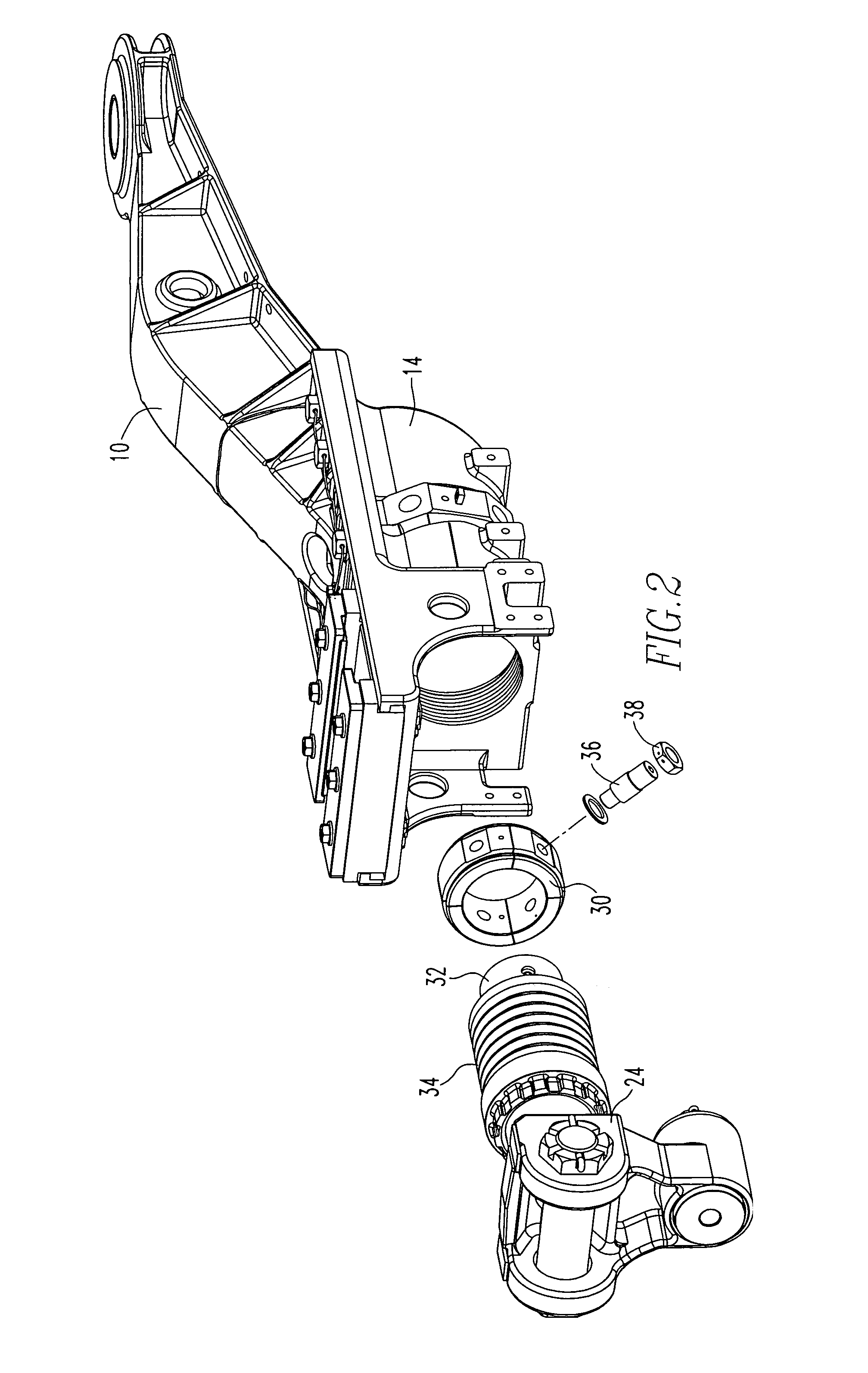
[0014]A plurality of emergency release bolts designed to shear under emergency buffing forces has threaded ends. There is a flat radial bearing surface between the ends of the emergency release bolts. When the release ring is positioned in the draft gear housing, release bolts may extend through the draft gear housing and into the sections of the release ring so that a flat surface extending radially from the release bolt will abut a flat chord surface of a release ring section establishing a well-defined shear plane. Nuts draw the sections radially outward minimizing flexing of the release bolts. The plurality of emergency release bolts directed radially through openings in the draft gear housing and corresponding to threaded holes in the sections of the emergency release ring enable each section to be drawn tightly against the inside surface of the draft gear housing facilitating pure longitudinal shearing load.
[0016]A plurality of release bolts designed to shear under emergency buffing forces has threaded ends. When the release ring is positioned in the draft gear housing, release bolts may extend through the draft gear housing and into the threaded bore in the sections of the release ring. A nut turned on the other threaded end of the release bolts draws the section radially outward to the interior wall of the draft gear housing eliminating any gap and thus minimizing flexing of the release bolts.

Problems solved by technology

At this time, the emergency release bolts will break or shear.
This bending results in reduction in the fatigue strength of the bolts.

Method used


Image

  • Fatigue-resistant emergency release device for rail transit vehicle coupler
  • Fatigue-resistant emergency release device for rail transit vehicle coupler
  • Fatigue-resistant emergency release device for rail transit vehicle coupler

Examples


Embodiment Construction

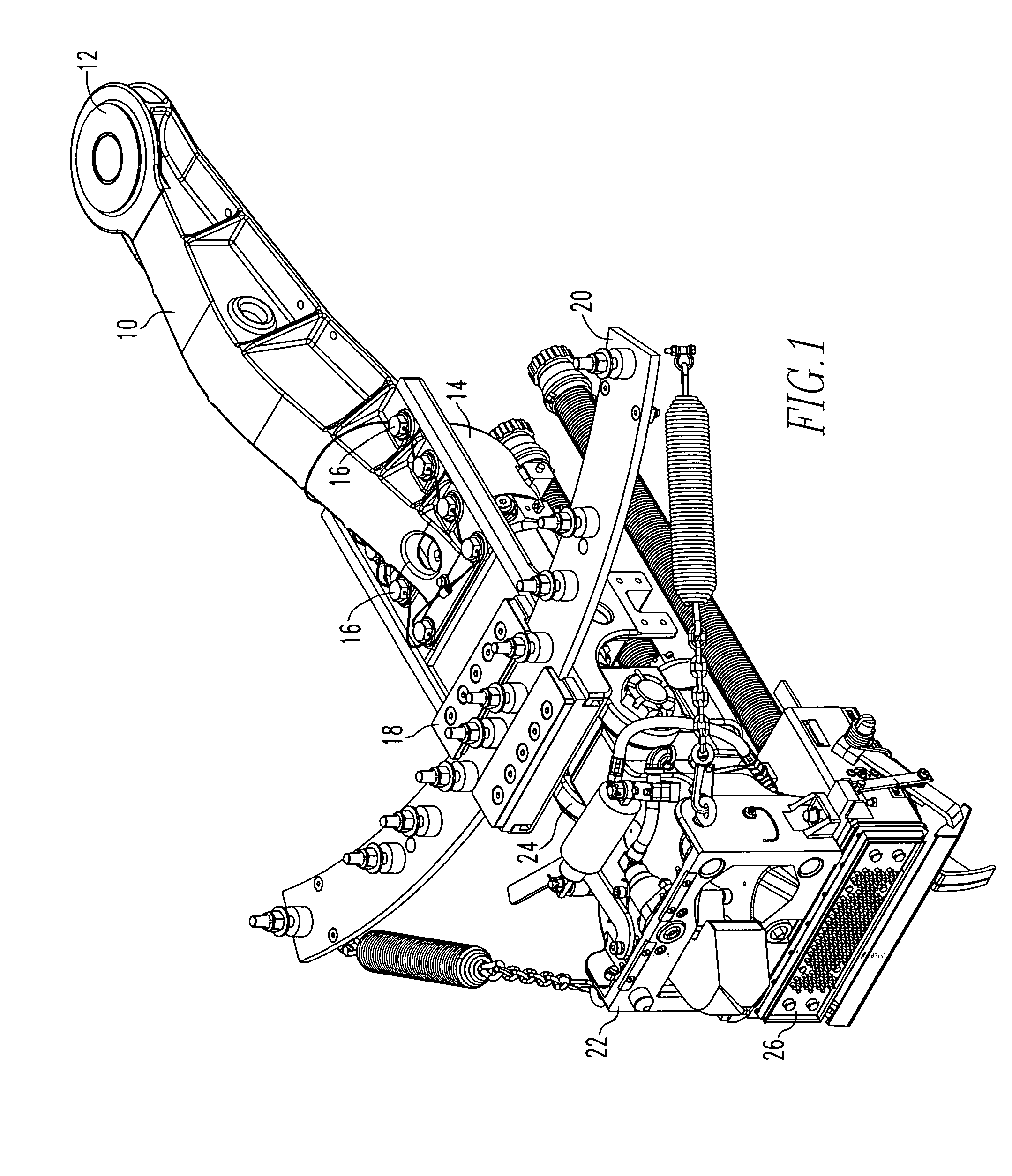
[0022]Referring now to FIG. 1, a mechanical connection between transit vehicles comprises a drawbar 10 that is secured to the underside of the vehicle (not shown) by an anchor ring 12 enabling rotation about a generally vertical axis. The draft gear housing 14 is bolted to the drawbar by secondary release bolts 16. On the upper side of the draft gear housing 14, a follower slot 18 is supported to receive a curved guide rail 20 secured to the underside of the vehicle which also accommodates the rotation of the drawbar 10 and draft gear housing 14 about the vertical axis through the anchor ring 12. A coupler head 22 for capturing the coupler head of an adjacent vehicle is mounted to a yoke 24 for rotation about a generally horizontal axis perpendicular to the axis of the drawbar 10. The yoke 24 is integral with a yoke shaft 32 (not visible in FIG. 1) which is journaled in the draft gear housing 14 for some rotation about a horizontal axis parallel to the axis of the drawbar 10. The yo...


PUM


Abstract

A release device for a draft gear assembly comprises a draft gear housing for slidably supporting a yoke shaft and capturing a cushion unit associated with the yoke shaft between buff and draft stops. The buff stop comprises a release ring within the interior of the draft gear housing being radially divided into two or more sections. A plurality of release bolts designed to shear under emergency buffing forces extend through the draft gear housing and into the sections of the release ring to draw the sections radially outward to the interior surface of the draft gear housing eliminating gaps and minimizing flexing of the release bolts.

Description

BACKGROUND OF THE INVENTION[0001]1. Field of the Invention[0002]This invention relates to the mechanical connection between rail vehicles and, in particular, between vehicles for carrying passengers in mass transit applications. This invention more specifically relates to the emergency release of the draft gear or cushioning assembly permitting the vehicles to come together for more controlled absorption of energy and to prevent climbing after collision.[0003]2. Description of Related Art[0004]In railway and transit vehicles, buffing and draft forces between connected vehicles are transmitted to the under frames of the vehicles through drawbars, draft gears and coupler heads (coupler assemblies). The draft gears have cushioning devices which accommodate normally expected forces. Adjacent vehicles are held coupled spaced apart. In the case of abnormal buffing forces which might be encountered on collision, it is desirable to enable the vehicles to come together so that anti-climbers ...

Claims


Application Information

Patent Timeline
Patent Type & Authority Patents(United States)
IPC IPC(8): B61G1/22
CPCB61G7/14B61G9/22
Inventor STEPP, JERRY LEE
Owner WABTEC HLDG CORP
Learn More