Wear Optimized Pad Design

Active Publication Date: 2017-03-09
BENDIKS SPAJSER FAUNDEJSHN BREJK LLK
View PDF0 Cites 3 Cited by
  • Summary
  • Abstract
  • Description
  • Claims
  • Application Information

AI Technical Summary

Benefits of technology

[0008]Another further advantage of the present invention is that the reduced width in the radially inner region of the brake pad permits the abutment faces of the brake pad carrier and the lateral sides of the brake pad to meet along a line that is more nearly perpendicular to a radius from the rotation axis. This arrangement allows the transfer braking forces between the lateral side of the brake pad and pad abutment surface of the pad carrier at or nearly normal to the abutment line. This provides for more uniform distribution of the abutment forces over the abutment surface, i.e., more even (and thus lower) contact pressures, helping minimize brake pad vibrations and associated brake noise, improved fatigue life performance and reduce component wear.
[0009]In addition, the arrangements can help in reducing the effects of “pad kick,” an in-place rotation of the brake pad that can generate undesired brake application noise due to pad vibrations, increase fatigue damage to typical brake pad retaining hardware (e.g., over-pad leaf springs) and increase wear and damage to the brake pad and/or brake caliper mounting structure. An illustration of pad kick is provided in FIG. 4. When a brake pad 101 is applied against a friction surface of a brake disk (not illustrated) which is rotating in direction DR, the brake disk's rotation induces motion and reaction forces between the brake pad 101 and its adjacent mount abutment surfaces (not illustrated). At the leading edge 102 of the brake pad the brake pad attempts to move upward in direction LU in response to the friction forces along the face of the brake pad (illustrated here by force a

Problems solved by technology

In disc brake applications such as commercial vehicle disc brakes the brake pads typically have had a generally rectangular shape, in part due to the limitations on the size and configuration of the disc brake components (the disc brake having to exist within a highly-space constrained envelope provided by wheel rims), and in part due to cost and structural limitations discussed further below.
As a result, the energy transfer to the brake pad, and the resulting localized wear of the brake pad, is inconsistent across the face of the brake pad friction material.
This can lead to premature wear of the friction material in some areas of the brake pad and th

Method used


Image

  • Wear Optimized Pad Design
  • Wear Optimized Pad Design
  • Wear Optimized Pad Design

Examples


Example

DETAILED DESCRIPTION OF THE DRAWINGS

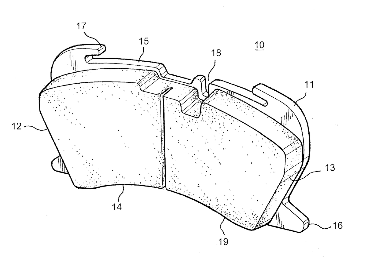
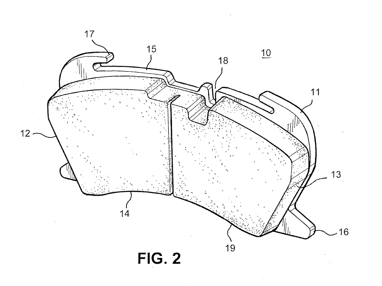
[0018]FIG. 2 is an oblique view of an embodiment of the present invention in which a brake pad 10 includes a backing plate 11 with brake pad friction material 19 affixed thereon. The lateral sides 12, 13 of the brake pad 10 are generally aligned, as shown in FIG. 3, along radii extending from the rotation axis of the brake disc 2 (not illustrated). The radially inner side 14 and the radially outer side 15 of the brake pad 10 are slightly curved, generally following the curvature of the brake disc.

[0019]The brake pad backing plate in this embodiment includes lateral projections 16 which are formed to engage corresponding brake pad retention features in the carrier mount 4 in the manner disclosed in co-pending application Ser. No. 14 / 640,152, such that even in the absence of any additional brake pad retention devices, once engaged in the carrier mount's receiving features the brake pad is positively retained within the disc brake. The backing plate ...


PUM


Abstract

A brake pad for a disc brake with decreased wear characteristics is provided. The brake pad is configured with the distribution of brake pad friction material weighted toward the radially outer region of the brake pad, with the lateral sides of the pad material being generally aligned with radial lines originating at the rotation axis of the brake disc of the disc brake. The brake pad friction material distribution results in decreased brake application pressure between the brake pad and the brake disc while obtaining the same braking force provided by a comparable generally rectangular brake pad, resulting in lower brake pad wear at the same braking force levels.

Description

BACKGROUND AND SUMMARY OF THE INVENTION[0001]The present invention relates to disc brakes for vehicles, and in particular to brake pads in disc brakes, such as air-operated disc brakes utilized on commercial vehicles.[0002]An example of a commercial vehicle air-operated disc brake is shown in FIG. 1. In the FIG. 1 embodiment the disc brake 1 includes a brake disk 2 which rotates in direction A about its rotation axis B. A brake caliper 3 straddling the brake disk 2 is affixed to a carrier mount 4 which in turn is fixed to a vehicle axle, typically via a torque plate or a brake spider (not illustrated). In this embodiment the carrier mount 4 receives and supports both the caliper 3 and the brake pads 6. The caliper 3 is actuated in this embodiment by a pneumatic actuator (not illustrated) mounted at the actuator mounting face 5 of the caliper. The actuator acts upon a brake pad application mechanism contained within caliper 3 to press the brake pads 6 against the brake disk 2 to slow...

Claims


Application Information

Patent Timeline
IPC IPC(8): F16D65/092F16D55/225
CPCF16D55/225F16D65/092F16D2065/026B60T1/065F16D55/22F16D65/095F16D69/00
Inventor SABETI, MANOUCHEHR
Owner BENDIKS SPAJSER FAUNDEJSHN BREJK LLK
Why Eureka
Try Eureka