
Method for managing network traffic related to a mechanism for signaling the presence of a terminal

a terminal and network traffic technology, applied in the field of telecommunications, can solve the problems of increasing traffic, increasing resource consumption, and adding reporting traffic, and achieve the effects of increasing the number of presence reporting areas, reducing the traffic due to the presence reporting mechanism, and increasing the load on the mobility management entity

Active Publication Date: 2021-08-03
ORANGE SA (FR)
View PDF15 Cites 0 Cited by
  • Summary
  • Abstract
  • Description
  • Claims
  • Application Information

AI Technical Summary

Benefits of technology

The patent describes a method to reduce network traffic by assigning a priority level to each presence reporting area and suspending the reporting mechanism when the network is overloaded. This allows the mobility management entity to regain a load that is non-critical for the network. The control entity is informed about which presence reporting areas are no longer monitored and can take action accordingly. This method restricts the additional traffic generated by sending these notifications to the highest priority levels.

Problems solved by technology

However, this multiplication of the presence reporting areas associated with a subscriber has a number of drawbacks.
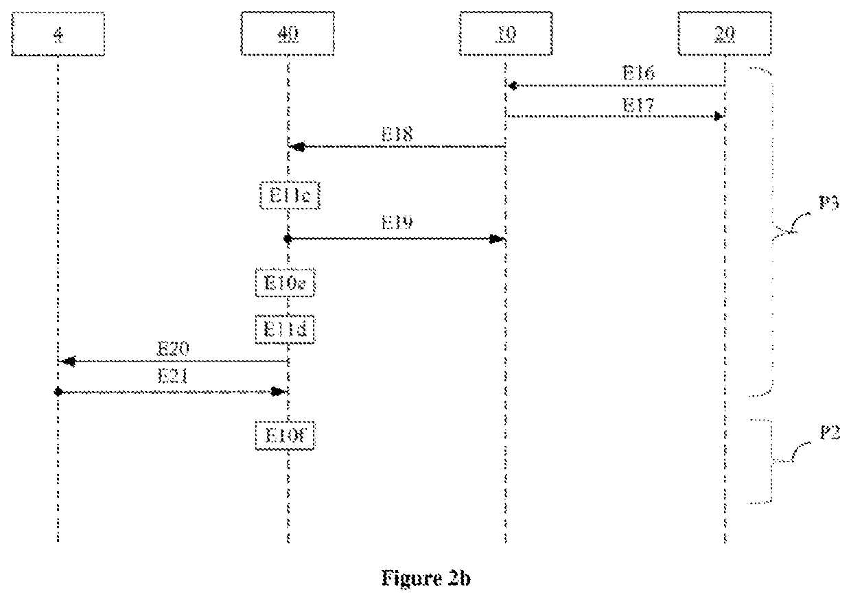
It gives rise to additional reporting traffic and higher resource consumption, notably at the entity responsible for managing mobility procedures within the network (such as an MME, for “Mobility Management Entity”).
Such an increase in traffic is liable, in particular, to create overloading of the network, or to aggravate an existing network overload.
Since the reporting messages related to the presence reporting mechanism sent by the mobility management entity are also relayed to entities such as a control entity (the PCRF entity, for example) or such as a subscriber credit management entity (the OCS entity, for example), the suspension of the reporting mechanism results in a lightening of the network traffic, both at the mobility management entity itself and at the network equipment required to relay the presence reporting information.

Method used


Image

  • Method for managing network traffic related to a mechanism for signaling the presence of a terminal
  • Method for managing network traffic related to a mechanism for signaling the presence of a terminal
  • Method for managing network traffic related to a mechanism for signaling the presence of a terminal

Examples


Embodiment Construction

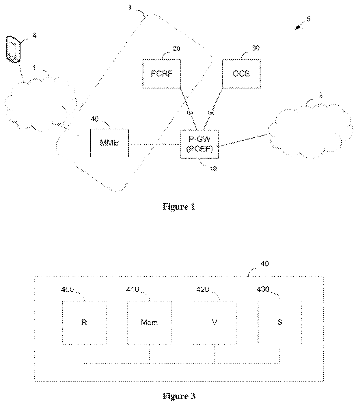
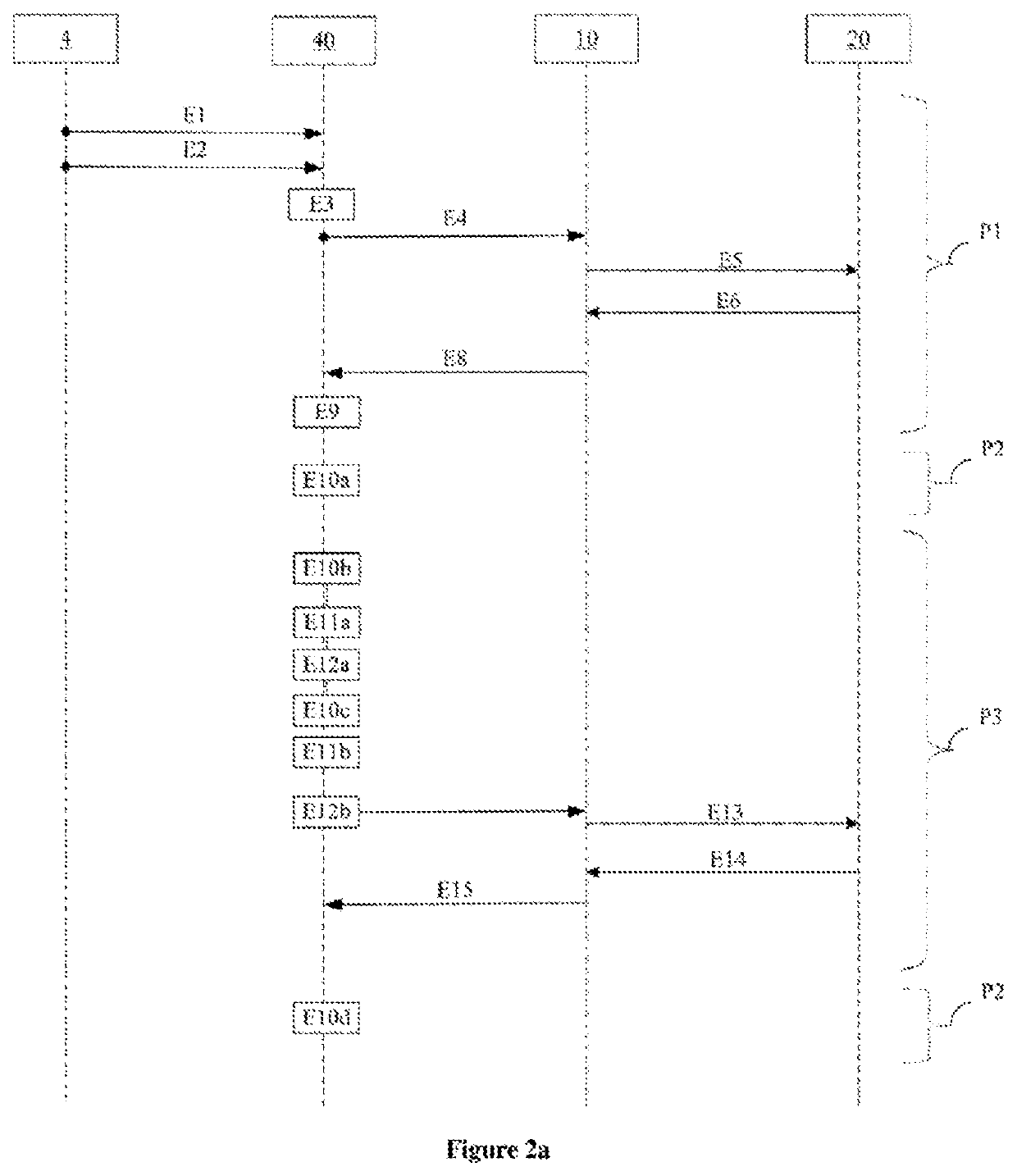
[0045]FIG. 1 shows a system 3 for managing the network traffic related to a mechanism for reporting the presence of a terminal 4 in a plurality of presence reporting areas of a communication network 5. This communications network 5 is, for example, an EPS (for “Evolved Packet System” in English) network. The terminal 4 accesses the communication network 5 via a mobile access network 1.

[0046]More particularly, the system 3 makes it possible to report a change of location, relative to a presence reporting area, of the terminal 4 for which a communication session is established with a packet communication network 2. The change of location corresponds to an entry or departure of the terminal 4 into or from a presence reporting area of a plurality of presence reporting areas associated with the terminal 4. Such a reporting area is typically a geographic area defined by one or more cells of the mobile access network 1.

[0047]The system 3 is integrated into a PCC architecture and comprises ...


PUM


Abstract

A method for managing, in a communication network, network traffic related to a mechanism for signaling the presence of a terminal in a plurality of presence-signaling areas. A mobility management entity receives, for each presence-signaling area of the plurality, an area identifier and a priority level for the area then stores, in a piece of subscriber context related to a subscriber of the terminal, the identifiers and priority levels received in association with an identifier of the terminal. When the load of the mobility management entity is higher than a predefined critical load threshold, the entity suspends the presence-signaling mechanism for the presence-signaling areas, referred to as non-monitored areas, of the plurality in which the priority level is lower than a transitional priority level.

Description

CROSS-REFERENCE TO RELATED APPLICATIONS[0001]This Application is a Section 371 National Stage Application of International Application No. PCT / FR2016 / 052879, filed Nov. 7, 2016, the content of which is incorporated herein by reference in its entirety, and published as WO 2017 / 081393 on May 18, 2017, not in English.FIELD OF THE DISCLOSURE[0002]The invention lies within the general field of telecommunications. More particularly, it concerns a method for managing network traffic related to a mechanism for reporting the presence of a terminal in a communication network.BACKGROUND OF THE DISCLOSURE[0003]The specification document TS 23.203 of the 3GPP (for “3rd Generation Partnership Project”) standardization group, version 13.2.0, defines an architecture called PCC (for “Policy and Charging Control” in English) architecture, for providing dynamic control of network resources on the basis of information collected by a control entity called a PCRF (for “Policy Control and Charging Rules F...

Claims


Application Information

Patent Timeline
Patent Type & Authority Patents(United States)
IPC IPC(8): H04W28/02H04L29/08H04W64/00
CPCH04W28/0226H04L67/24H04W64/006H04W28/0247H04L47/245H04L47/2458H04L67/52H04L67/54
Inventor MOUAFIK, ALI-AMINEMOUQUET, ANTOINEEL MOUMOUHI, SANAA
Owner ORANGE SA (FR)
Learn More