Network system with shared filtering information

a network system and information filtering technology, applied in the field of network systems, can solve the problems of unauthorized access, web servers and ftp servers that exist on the network and implement information transferring services, and the corporate network is vulnerable to threats, so as to achieve the effect of improving security and lightening network load

Inactive Publication Date: 2005-09-15
FUJITSU LTD
View PDF3 Cites 6 Cited by
  • Summary
  • Abstract
  • Description
  • Claims
  • Application Information

AI Technical Summary

Benefits of technology

[0021] This invention's network system is structured so that when filtering information is to be shared, if the filtering information has a destination address, and the receiving port of the filtering information matches the relay destination ports of the destination addresses, and if there is only one relay destination port for the destination address, filtering information shall be registered on its own device and then relayed to an adjacent device, but if there is no destination address information in the filtering information sent from the adjacent device through the filtering sharing conditions, the receiving port of the filtering information shall be registered onto itself as also the destination port, and filtering information will not be relayed to an adjacent device. Through this method, filtering information can be effectively shared throughout an entire network, advanced filtering can be achieved, and it becomes possible for the network load to be lightened and security to be improved.

Problems solved by technology

Currently, corporate networks are vulnerable to threats such as unauthorized access.
Such threats are not limited to corporate networks, as web servers and FTP (File Transfer Protocol) servers that exist on a network and implement information transferring services are also vulnerable.
As mentioned above, if filtering is set up on a relay device in a network, the filtering is only effective on that particular device, and does not run until a frame to be filtered arrives to that device.
Thus, frames will be relayed through the network until they arrive at that particular device even if they are frames to be discarded, causing an excess load problem.
In this manner, when filtering is set up on individual devices, excess relay flow occurs.
Although filtering information can be set up for the entire network and not individual devices (for example, in the example mentioned above, filtering settings would be applied to all Relay Devices 61˜66 in order to filter access to Server 80 from Computer Terminals 73, 75, and 76), so that an excess load would not occur, but, in this case, it would be very tedious to reset if filtering settings were ever to change.
Also, with regards to filtering content, flow that is not to be filtered would be subject to filtering if other devices were to have filtering set up, posing a risk for setup errors in addition to the process being unrealistic.
Meanwhile, on servers to date, filtering is applied through access restrictions set up by a server application, but an error had occurred in the past in which a focused access attack could not be prevented regardless of access restrictions.
In particular, setting up access restrictions only to the server alone is useless towards unauthorized access such as Denial of Service Attacks (DOS (Denial of Service) Attack: A user with bad intentions submits a large amount of connection requests to the server, depleting server resources so that connection service is stopped for legitimate users), and even if a firewall stops a device, the access focused on that server will eat away the server resources mid-process, stopping all other communication.
Also, the current technology's filtering tables are simply structured with a combination of address and destination ports, so a filtering control with an advanced protocol cannot be used to exchange several commands between devices.

Method used


Image

  • Network system with shared filtering information
  • Network system with shared filtering information
  • Network system with shared filtering information

Examples


Embodiment Construction

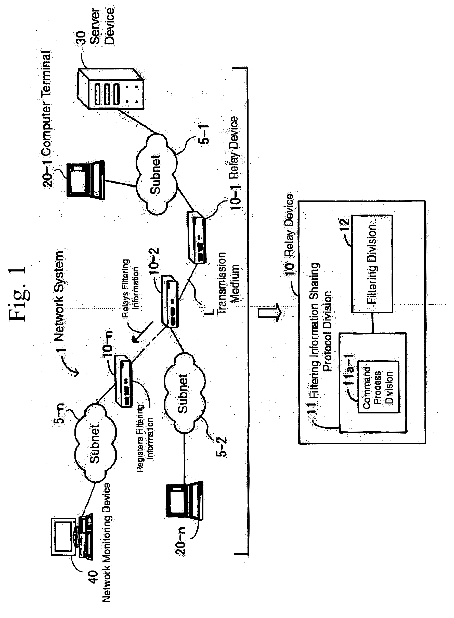
[0045] The following explanation uses drawings of this invention's working form as reference. FIG. 1 is a fundamental drawing of this invention's network system. Network System 1 uses Transmission Medium L (can be either with wires or wireless) to connect each structural device; consists of Relay Devices 10-1˜10-n (general term “Relay Device 10”), Computer Terminals 20-1˜20-n, Server Device (hereinafter “Server”) 30, Network Monitoring Device 40, and Subnet 5-1˜5-n; and is a system that applies filtering on a network and transmits frames (or packets, cells. This invention will unify these terms).

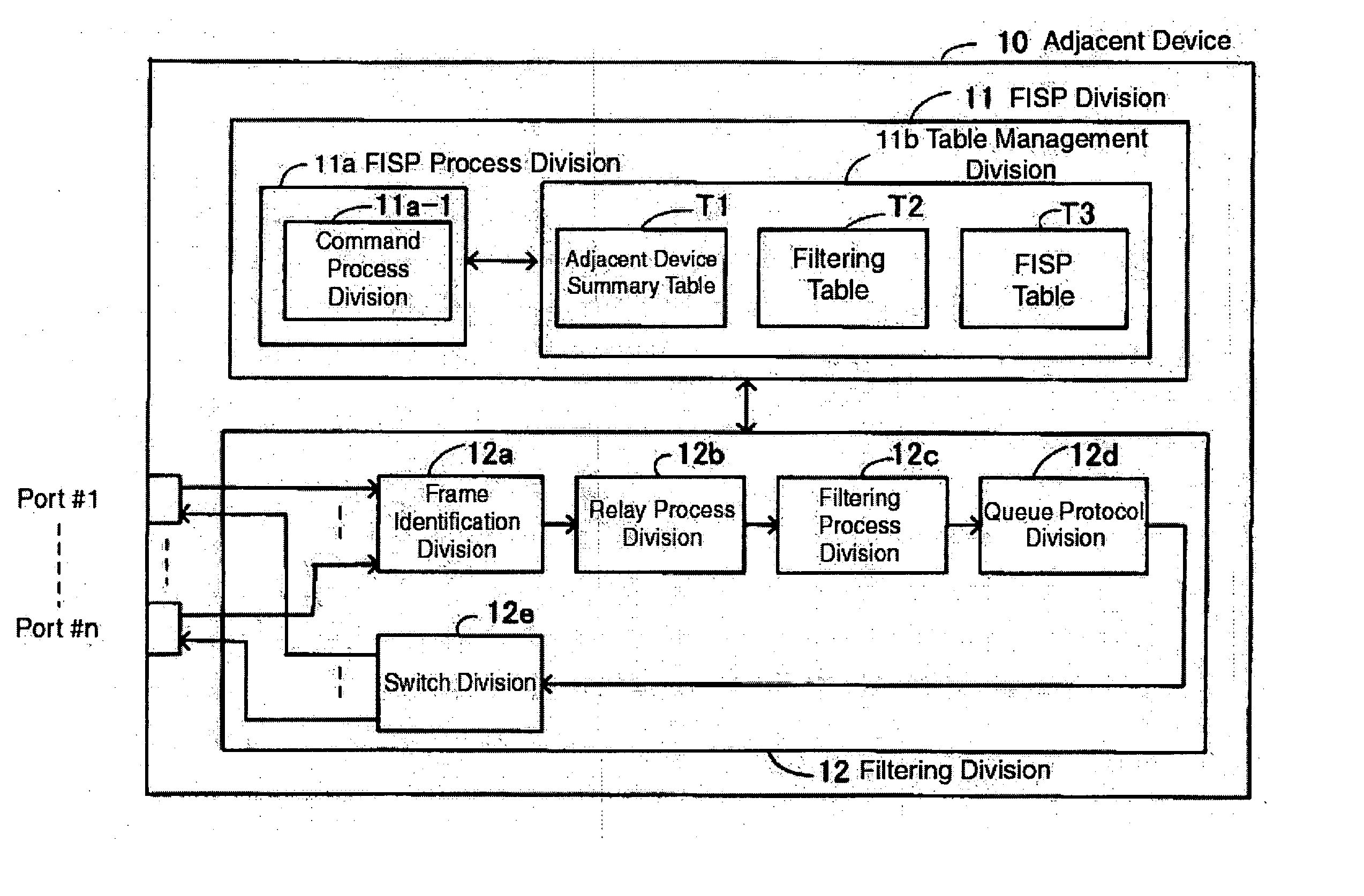
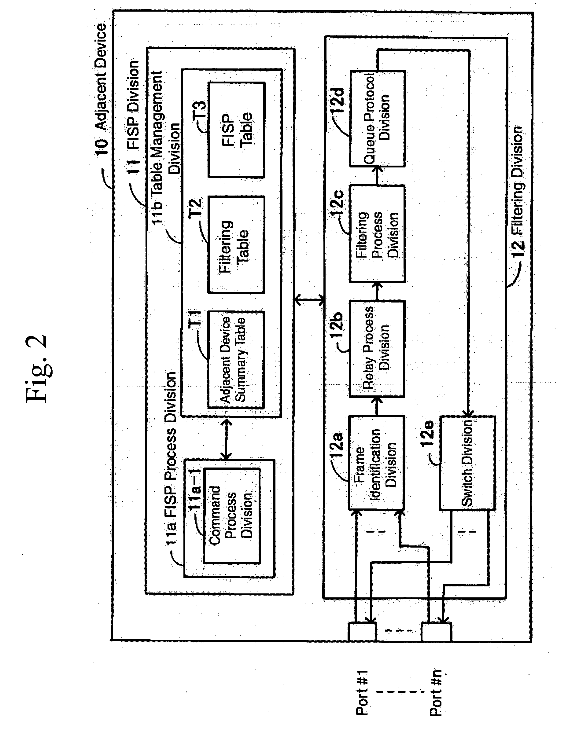
[0046] Relay Device 10 consists of Filtering Information Sharing Protocol Division 11 and Filtering Division 12, and Filtering Information Sharing Protocol Device 11 includes Command Process Division 11a-1.

[0047] Command Process Division 11a-1 generates and parses commands that include filtering information for the sharing of necessary filtering information on the entire network. Filtering...


PUM


Abstract

A network system comprising a transmission medium coupling a plurality of devices on the network, a plurality of relay devices connected to the transmission medium, each relay device operable to apply filtering on data from the network and transmits frames, each relay device comprising command process division operable to generate and parse commands that include filtering information relating the sharing of filtering information on the network, and when filtering sharing conditions are applied, register filtering information on its own device and apply a protocol to relay to an adjacent device if filtering information sent from an adjacent device through the filtering sharing conditions has a destination address, if a port that received the filtering information from the adjacent matches a relay destination port of the destination address, and if there is only one relay destination port for the destination address, register a receiving port of the filtering information as a destination port, if there is no destination address information in the filtering information sent from the adjacent device through the filtering sharing conditions, and a filtering information sharing protocol division operable to apply a protocol so that filtering information is not relayed to an adjacent device, and a filtering division operable to relay filtering information and frames, or filters discarded information, based on instruction from the filtering information sharing protocol division.

Description

BACKGROUND OF THE INVENTION [0001] 1. Field of the Invention [0002] This invention is related to network systems, particularly network systems that transmit frames after applying filtering on a network. [0003] 2. Background of the Prior Art [0004] Currently, corporate networks are vulnerable to threats such as unauthorized access. Such threats are not limited to corporate networks, as web servers and FTP (File Transfer Protocol) servers that exist on a network and implement information transferring services are also vulnerable. Networks need to prevent unauthorized access and the destruction of internal data by deploying a firewall, or setting up a protective mechanism on relaying devices such as routers or switches. [0005] Mechanisms that protect against unauthorized access generally use a filtering function. This function is structured to ensure security by examining frames sent through the network, determining whether to permit access, and then discarding frames that have been de...

Claims


Application Information

Patent Timeline
Patent Type & Authority Applications(United States)
IPC IPC(8): H04L12/66G06F15/173H04L12/46
CPCH04L12/6418H04L63/1458H04L63/0218
Inventor NAMIHIRA, DAISUKE
Owner FUJITSU LTD
Why Eureka
Try Eureka