Image forming device, paper feeding mechanism deterioration determining method and non-transitory recording medium

a paper feeding mechanism and deterioration determining technology, which is applied in the direction of electrographic process, instruments, transportation and packaging, etc., can solve the problems of paper feeding mechanism jams and low paper conveyance capacity, and achieve the effect of determining wear and deterioration status of paper feeding mechanism more accurately

Active Publication Date: 2021-10-12
KONICA MINOLTA INC
View PDF4 Cites 0 Cited by
  • Summary
  • Abstract
  • Description
  • Claims
  • Application Information

AI Technical Summary

Benefits of technology

[0011]The present invention is intended to solve the above problems. Thus, the present invention is intended to provide an image forming device, a paper feeding mechanism deterioration determining method and a non-transitory recording medium that correct a measured value while considering whether or not multifeeding occurs at paper feeding so that determining wear and a deterioration status of a paper feeding mechanism more accurately than conventional ones.

Problems solved by technology

When a paper feeding operation is repeatedly performed in the image forming device, parts such as the paper feeding roller is worn and deteriorated, resulting in lower sheets conveyance capacity of the paper feeding mechanism.
If wear and the deterioration status of the paper feeding mechanism is left as it is, jams easily occur at feeding of papers.

Method used


Image

  • Image forming device, paper feeding mechanism deterioration determining method and non-transitory recording medium
  • Image forming device, paper feeding mechanism deterioration determining method and non-transitory recording medium
  • Image forming device, paper feeding mechanism deterioration determining method and non-transitory recording medium

Examples


first preferred embodiment

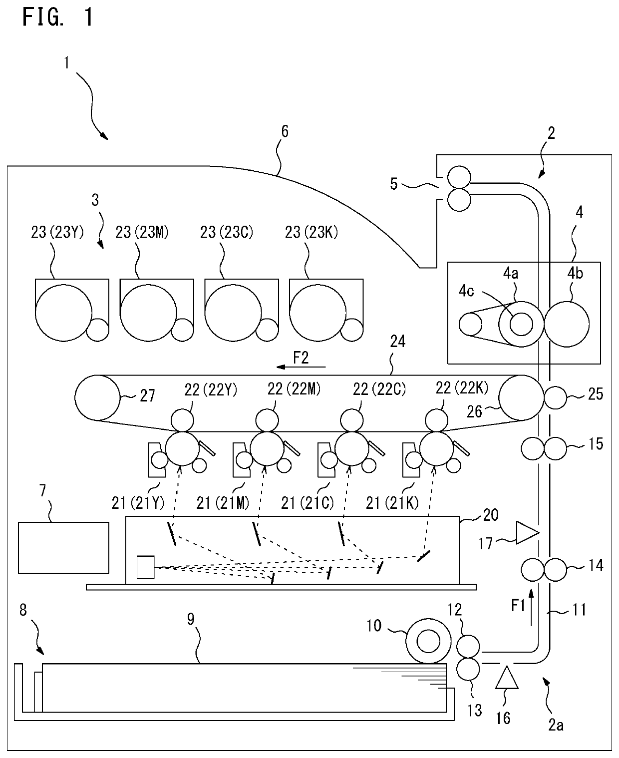
[0041]FIG. 1 illustrates an exemplary conceptual configuration of an image forming device 1 in which the first preferred embodiment of the present invention may be practiced. The image forming device 1 of FIG. 1 is a printer capable of forming color images in tandem system. The image forming device 1 includes a paper feeding unit 2, an image forming unit 3 and a fixing unit 4 inside a device body. The image forming device 1 forms a color image or a black and white image on a sheet 9 such as a print paper, and delivers the sheet 9 on a paper delivery tray 6 from a paper delivery port 5 provided in an upper part of the device body. The image forming device 1 includes a controller 7 inside the device body. The controller 7 controls operations of each part such as the paper feeding unit 2, the image forming unit 3 and the fixing unit 4.

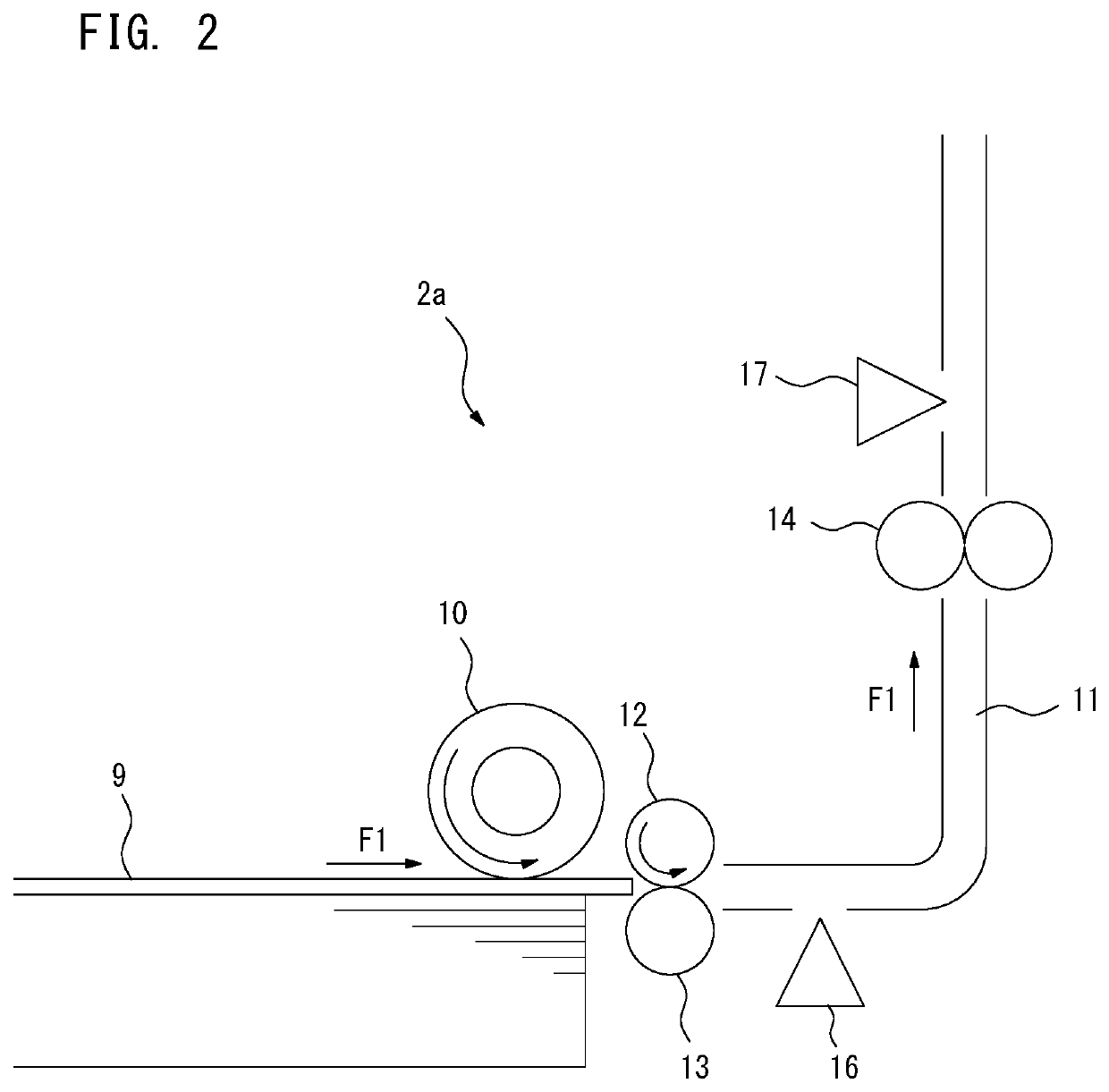
[0042]The paper feeding unit 2 includes a paper feeding tray 8, a paper feeding mechanism 2a, a carrying path 11, a resist roller 15 and a secondary tran...

second preferred embodiment

[0115]The second preferred embodiment of the present invention is explained next. In the above-described first preferred embodiment, the correction coefficient C is calculated based on the data (passing time) measured at feeding of the paper. The progress of wear and the deterioration of the paper feeding mechanism 2a is correlated with the number of the paper fed by the paper feeding mechanism 2a. Thus, the correction coefficient C corresponding to the number of the fed paper is calculated in advance, and the calculated correction coefficient C may be stored as information such as a table. In the second preferred embodiment, the correction coefficient C corresponding to the number of the fed paper is stored in advance.

[0116]FIG. 15 illustrates a block diagram showing an example of a hardware structure and a functional structure of the controller 7 in which the second preferred embodiment may be practiced. The difference between the controller 7 of FIG. 15 and the controller 7 of th...

third preferred embodiment

[0124]The third preferred embodiment of the present invention is explained next. As described above, once the type of the sheet 9 fed by the paper feeding mechanism 2a is changed, the carrying speed of the sheet 9 may also be changed. In the third preferred embodiment, the correction coefficient C corresponding to the carrying speed (feeding speed) of the sheet 9 is kept.

[0125]FIG. 19 illustrates an example of the relation between the type of the sheet 9 and the carrying speed. A speed reduction setting may be configured with the image forming device 1 of FIG. 19. The speed reduction setting is applied, for instance, when the print job executed by the image forming device 1 is to produce printed outputs using the multiple types of the sheets 9. On and off may be configured as the speed reduction setting. When the speed reduction setting is off, the carrying speed appropriate for the changed type of the sheet 9 is set as usual once the type of the sheet 9 is changed during processing...


PUM


Abstract

An image forming device comprising: a tray in which multiple number of sheets are stored; a feeder that feeds the sheet stored in the tray; and a hardware processor that: measures a carrying speed of the sheet fed by the feeder; determines whether or not the measured carrying speed is affected by the following sheet; corrects the carrying speed upon determining the carrying speed is affected by the following sheet; and detects a wear status on the feeder based on the measured carrying speed or the corrected carrying speed.

Description

[0001]Japanese patent application No. 2018-198938 filed on Oct. 23, 2018 including description, claims, drawings, and abstract the entire disclosure is incorporated herein by reference in its entirety.BACKGROUNDTechnological Field[0002]The present invention relates to an image forming device, a paper feeding mechanism deterioration determining method and a non-transitory recording medium. The present invention more specifically relates to a technique for determining wear and a deterioration of the paper feeding mechanism that feeds sheets.Description of the Related Art[0003]Image forming devices such as printers or MFPs (Multifunction Peripherals) includes paper feeding mechanisms that feed sheets such as print papers. The paper feeding mechanism includes a paper feeding roller to feeds the sheet. The paper feeding mechanism rotates the paper feeding roller in a predetermined direction so that the sheet is fed toward a predetermined carrying path. When a paper feeding operation is r...

Claims


Application Information

Patent Timeline
Patent Type & Authority Patents(United States)
IPC IPC(8): B65H7/18B65H7/02B65H5/06B65H7/20B65H43/00B65H3/06
CPCB65H7/18B65H3/06B65H5/06B65H7/02B65H7/20B65H43/00B65H2301/4234B65H2511/30B65H2511/524B65H2513/10B65H2513/53B65H2515/842B65H2601/121G03G15/75G03G15/6532B65H2801/06B65H7/12B65H2557/652B65H3/5215B65H2513/52B65H2515/84B65H2220/03B65H2220/01B65H2220/11
Inventor HITAKA, MASATOSHI
Owner KONICA MINOLTA INC
Why Eureka
Try Eureka