Implant placement

a technology for implants and bone, applied in the direction of prosthesis, patient positioning for diagnostics, application, etc., can solve the problem that the density of the bone in different portions of the sacrum is not typically a consideration

Active Publication Date: 2021-10-19
SI BONE INC
View PDF744 Cites 6 Cited by
  • Summary
  • Abstract
  • Description
  • Claims
  • Application Information

AI Technical Summary

Problems solved by technology

However, the density of the bone in different portions of the sacrum is not typically a consideration during implant placement.

Method used


Image

  • Implant placement
  • Implant placement
  • Implant placement

Examples


Embodiment Construction

[0070]Pre-op Preparation and Patient Setup

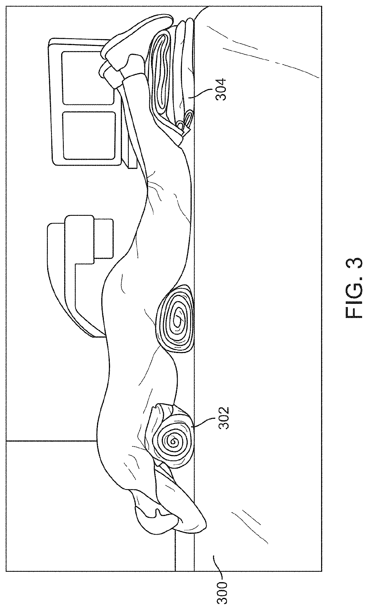
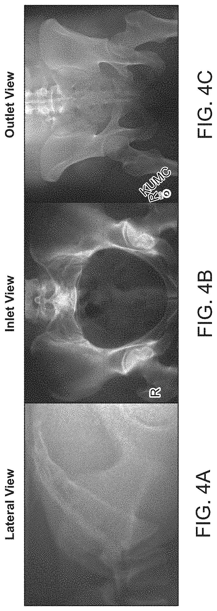
[0071]A computed tomography (CT) scan may be taken of the pelvis and SI-Joints prior to surgery to check for anatomic anomalies and to identify osseous landmarks useful for implant placement. The patient may be placed on a flat radiolucent table, such as a Jackson table, to facilitate intra-operative imaging. Although one C-arm is typically employed, some surgeons may employ two C-arms, with one C-arm set in the lateral position and the other C-arm rotatable between the inlet and outlet positions, as further described below. As illustrated in FIG. 3, the patient may be placed on a flat Jackson type imaging table 300 with towel rolls 302 or other support structures placed transversely under the patient's chest and waist. This position allows the abdomen to hang free resulting in diminished intraabdominal pressure. Pillows 304 or other support structures can be placed under the patient's feet to relax the knees. After the patient has been prop...


PUM


Abstract

Embodiments of the present invention relate generally to implant placement into bone. More specifically, embodiments of the invention relate to implant placement across the sacro-iliac joint. Placement can be facilitated using various CT imaging views that allow the implants to be placed in bone associated with articular cartilage.

Description

CROSS REFERENCE TO RELATED APPLICATIONS[0001]This application is a continuation-in-part of U.S. application Ser. No. 14 / 515,416, filed Oct. 15, 2014, now U.S. Pat. No. 9,839,448, which claims priority to U.S. Provisional Patent Application No. 61 / 891,326, filed Oct. 15, 2013, and titled “IMPLANT PLACEMENT,” which is herein incorporated by reference in its entirety for all purposes.INCORPORATION BY REFERENCE[0002]All publications and patent applications mentioned in this specification are herein incorporated by reference to the same extent as if each individual publication or patent application was specifically and individually indicated to be incorporated by reference.FIELD[0003]Embodiments of the invention relate generally to implant placement into bone. More specifically, embodiments of the invention relate to implant placement across the sacro-iliac joint.BACKGROUND[0004]Many types of hardware are available both for the fixation of bones that are fractured and for the fixation of...

Claims


Application Information

Patent Timeline
Patent Type & Authority Patents(United States)
IPC IPC(8): A61F2/46A61B6/12A61B6/03A61B6/00A61B17/68A61B17/16A61F2/30A61B6/04A61B17/92A61B17/88
CPCA61F2/4603A61B6/032A61B6/12A61B6/4441A61B6/505A61B17/1659A61B17/68A61B6/0407A61B17/1637A61B17/1664A61B17/8897A61B2017/922A61F2002/30622A61F2002/30995A61F2002/4662A61F2002/4681
Inventor RECKLING, W. CARLTONREILEY, MARK A.YERBY, SCOTT A.FARLEY, SEANLEUNG, JOANNE
Owner SI BONE INC
Why Eureka
Try Eureka