Sacroiliac joint fusion systems and methods

a joint fusion and iliac joint technology, applied in the field of sacroiliac joint fusion systems and methods, can solve the problems of large operative time, large recovery time, and significant problems, and achieve the effects of improving the operative efficiency

Active Publication Date: 2020-09-22
BEACON BIOMEDICAL LLC
View PDF66 Cites 4 Cited by
  • Summary
  • Abstract
  • Description
  • Claims
  • Application Information

AI Technical Summary

Benefits of technology

[0009]In various exemplary embodiments, the present invention provides a portal tube, a drill guide tube, a drill guide, and implant guide tube, an implant, and related instrumentation for fusing or otherwise securing a sacroiliac or other joint via a minimally-invasive or open surgical procedure, with direct and / or indirect (i.e. fluoroscopy / radiography) visualization. These sacroiliac joint fusion systems and methods provide superior visualization of and access to the sacroiliac joint, provide very predictable and consistent results easily and efficiently, provide superior stabilization and / or fusion of the sacroiliac joint, as well as optional distraction and / or translation, if desired, and minimize surgical time, thereby eliminating the problems described above.
[0012]In a further exemplary embodiment, the present invention provides a joint fixation method, including: drilling a plurality of bores in a joint, wherein the plurality of bores collectively approximate a predetermined cross-sectional shape; and press fitting an implant having the predetermined cross-sectional shape in the plurality of bores drilled in the joint. The method also includes, prior to drilling the plurality of bores, disposing a portal tube adjacent to the joint, thereby providing access to and stabilizing the joint. The method further includes securing the portal tube to the joint using a guide pin. The method still further includes, prior to drilling the plurality of bores, disposing a drill guide tube concentrically within the portal tube and drilling the plurality of bores through the drill guide tube. Optionally, the method still further includes, prior to drilling at least some of the plurality of bores, disposing a drill guide concentrically within the drill guide tube. Optionally, the method still further includes, subsequent to drilling the plurality of bores, disposing an implant guide tube concentrically within the portal tube. The implant guide tube defines an internal channel that has a cross-sectional shape that substantially conforms to the predetermined cross-sectional shape of the implant, wherein the implant is disposed in the plurality of bores through the internal channel of the implant guide tube. Optionally, the implant is disposed in the plurality of bores through the implant guide tube using an elongate impaction tool that has a cross-sectional shape that substantially conforms to the cross-sectional shape of the internal channel of the implant guide tube. Optionally, the implant includes one or more recesses configured to hold a bone graft material. Optionally, the joint is a sacroiliac joint.

Problems solved by technology

Significant problems exist, especially when sacroiliac joint fusion is performed via an open surgical procedure, for example.
Open surgical procedures require general anesthesia and can involve considerable operative time, recovery time, hospitalization, and pain due to significant soft tissue damage.
Damage to blood vessels and nerves is also possible.
Specifically, the placement of a fixation assembly, an implant, and / or one or more screws can cause damage to the lumbosacral neurovascular elements and / or delayed union of the sacroiliac joint.
Minimally-invasive surgical procedures are technically more difficult and require multiplanar fluoroscopy / radiography of the articular surfaces of the sacroiliac joint, for example.
Again, the placement of a fixation assembly, an implant, and / or one or more screws can cause damage to the lumbosacral neurovascular elements and / or delayed union of the sacroiliac joint.
Further, sacral anomalies can lead to mal-placement of the implant, leading to damage to the surrounding structures.
Likewise, insufficient amounts of the articular surfaces and / or the cortical surfaces of the sacroiliac joint may be engaged by the fixation assembly, the implant, and / or the one or more screws to ensure adequate stabilization and / or fusion.
The failure to adequately stabilize and / or fuse the sacroiliac joint can result in a failure to relieve the condition being treated.
Mal-alignment of the sacroiliac joint is a similar problem and can lead to increased pain.

Method used


Image

  • Sacroiliac joint fusion systems and methods
  • Sacroiliac joint fusion systems and methods
  • Sacroiliac joint fusion systems and methods

Examples


Embodiment Construction

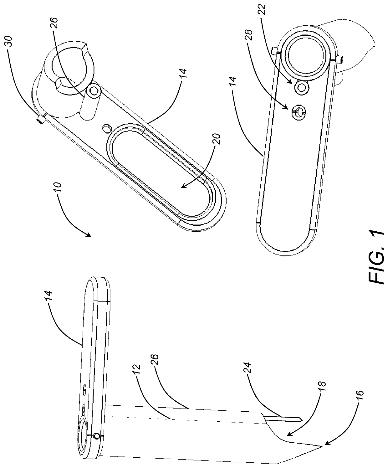
[0026]Again, in various exemplary embodiments, the present invention provides a portal tube, a drill guide tube, a drill guide, and implant guide tube, an implant, and related instrumentation for fusing or otherwise securing a sacroiliac or other joint via a minimally-invasive or open surgical procedure. These sacroiliac joint fusion systems and methods provide superior visualization of and access to the sacroiliac joint, provide very predictable and consistent results easily and efficiently, provide superior stabilization and / or fusion of the sacroiliac joint, as well as distraction and / or translation, if desired, and minimize surgical time, thereby eliminating the problems described above.

[0027]Referring now specifically to FIG. 1, in one exemplary embodiment, the portal tube 10 includes a cannulated access tube 12 and a handle 14 coupled to the proximal end of the access tube 12. The handle 14 is used to manipulate the access tube 12, as well as to secure other components inside ...


PUM


Abstract

Joint fixation systems and methods, enabling: drilling one or more major bores in a joint; drilling one or more minor bores in the joint, wherein the one or more minor bores are disposed about a periphery of and partially overlap the major bore(s); and disposing an implant in the major bore(s) and the one or more minor bores, wherein a cross-sectional shape of the implant substantially conforms to a collective cross-sectional shape of the major bore(s) and the one or more minor bores. Prior to drilling the major bore(s) or the one or more minor bores, a portal tube is disposed adjacent to the joint, thereby providing access to and stabilizing the joint. A drill guide tube is disposed concentrically within the portal tube, and a drill guide is disposed concentrically within the drill guide tube. Subsequent to drilling the major bore(s) and the one or more minor bores, an implant guide tube is disposed concentrically within the portal tube.

Description

CROSS-REFERENCE TO RELATED APPLICATIONS[0001]The present patent application / patent claims the benefit of priority of U.S. Provisional Patent Application No. 62 / 095,120, filed on Dec. 22, 2014, and entitled “SACROILIAC JOINT FUSION SYSTEMS AND METHODS,” and U.S. Provisional Patent Application No. 61 / 118,759, filed on Feb. 20, 2015, and entitled “SACROILIAC JOINT FUSION SYSTEMS AND METHODS,” the contents of both of which are incorporated in full by reference herein.FIELD OF THE INVENTION[0002]The present invention relates generally to sacroiliac and other joint fusion systems and methods. More specifically, the present invention relates to a portal tube, a drill guide tube, a drill guide, an implant guide tube, an implant, and related instrumentation for fusing or otherwise securing a sacroiliac or other joint via a minimally-invasive or open surgical procedure.BACKGROUND OF THE INVENTION[0003]The sacroiliac joint is the joint between the sacrum and the ilium of the pelvis. The sacrum...

Claims


Application Information

Patent Timeline
Patent Type & Authority Patents(United States)
IPC IPC(8): A61B17/70A61B17/88A61B17/02A61F2/46A61B17/17A61F2/30
CPCA61F2/4601A61B17/1757A61F2002/30995A61B17/3421A61B17/68A61B2017/0042A61B2017/922
Inventor LINS, ROBERT E.
Owner BEACON BIOMEDICAL LLC
Why Eureka
Try Eureka