
Laser sternotome

a sternotome and laser technology, applied in the field of cutting devices, can solve the problems of inability to afford many facilities where such an osteotome could be used, difficulty in fixing the cutting device, and high cost, and achieve the effects of convenient application, fast, gentle and easy fixation of the cutting device, and keeping the cut geometry and the room around it clean

Active Publication Date: 2022-02-15
ADVANCED OSTEOTOMY TOOLS - AOT
View PDF13 Cites 0 Cited by
  • Summary
  • Abstract
  • Description
  • Claims
  • Application Information

AI Technical Summary

Benefits of technology

The patent text describes a method for cutting the sternum in medical applications using a pulsed laser beam generated by a solid-state Erbium laser source. The use of pulsed laser beams allows for precise and efficient ablation of bone tissue with minimal collateral damage on the sternum. Additionally, the text suggests using a laser based photo-acoustic spectroscopy sensor to determine if the last shot encountered a hard or soft tissue, which can help to draw conclusions if the sternum is completely cut or not.

Problems solved by technology

This is particularly difficult since the sternum is a comparably thick and strong bone structure and, vital organs such as the heart and lung are in contact with it.
Furthermore, they usually are comparably costly such that many facilities where such an osteotome could be used cannot afford it.

Method used


Image

  • Laser sternotome
  • Laser sternotome
  • Laser sternotome

Examples


Embodiment Construction

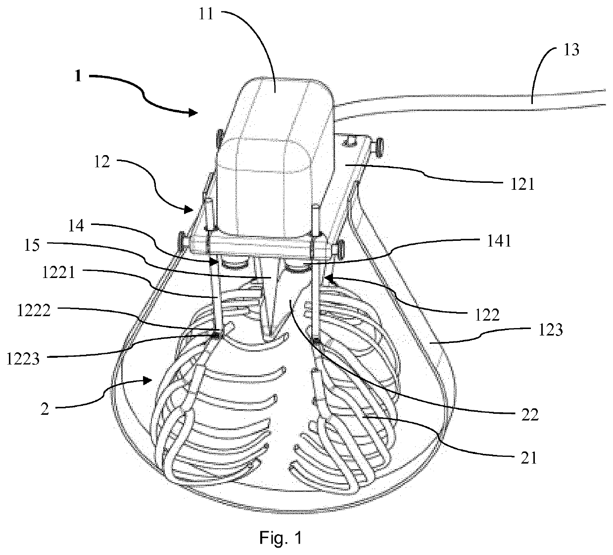
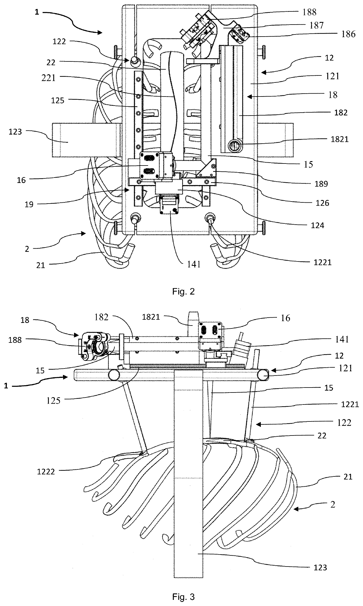
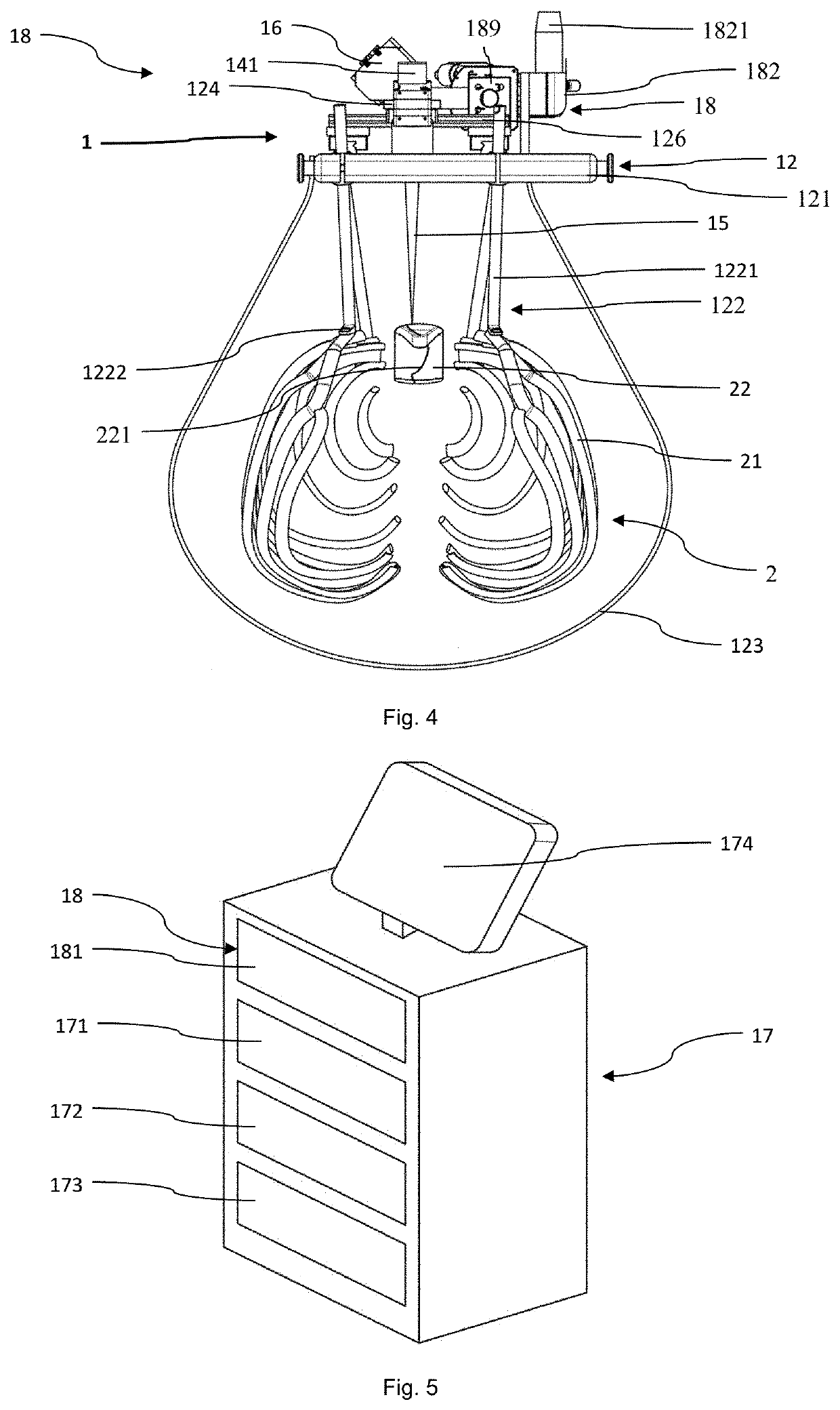
[0050]In the following description certain terms are used for reasons of convenience and are not intended to limit the invention. The terms “right”, “left”, “up”, “down”, “under” and “above” refer to directions in the figures. The terminology comprises the explicitly mentioned terms as well as their derivations and terms with a similar meaning. Also, spatially relative terms, such as “beneath”, “below”, “lower”, “above”, “upper”, “proximal”, “distal”, and the like, may be used to describe one element's or feature's relationship to another element or feature as illustrated in the figures. These spatially relative terms are intended to encompass different positions and orientations of the devices in use or operation in addition to the position and orientation shown in the figures. For example, if a device in the figures is turned over, elements described as “below” or “beneath” other elements or features would then be “above” or “over” the other elements or features. Thus, the exempla...


PUM


Abstract

A cutting device for cutting a sternum of a patient comprises a laser source, a beam adjusting structure, a support and a correction arrangement. The laser source is adapted to generate a cut laser beam. The beam adjusting structure is arranged for directing the laser beam along a predefined cut geometry at the sternum. The support carries the laser source. The support has a mounting structure adapted to be fixed to a rib cage of the patient such that the laser source is in a predefined position with respect to the sternum. The correction arrangement is adapted to automatically identify a movement of the laser source relative to the sternum causing the cut laser beam to deviate from the predefined cut geometry and adjust the position of the laser source relative to the sternum to correct the deviation of the cut laser beam with respect to the predefined cut geometry.

Description

CROSS-REFERENCE TO RELATED APPLICATION(S)[0001]This application is a national phase entry under 35 U.S.C. 371 of PCT Appl. PCT / EP2017 / 065372, filed Jun. 22, 2017, which claims priority to EP Appl. No. 16175604.4, filed Jun. 22, 2016, the entire contents of which are incorporated herein in their entirety.TECHNICAL FIELD[0002]The present invention relates to a cutting device comprising a laser source, a beam adjusting structure and a support. The laser source is adapted to generate a cut laser beam. The beam adjusting structure is adapted for directing the cut laser beam generated by the laser source along a predefined cut geometry at a sternum. The support carries the laser source. Such devices can be used for cutting a sternum of a patient in various medical applications.BACKGROUND ART[0003]In many medical applications human or animal bones are cut or drilled for various purposes. For example, for correcting the shape of a bone it is known to apply one or plural cuts to a bone and t...

Claims


Application Information

Patent Timeline
Patent Type & Authority Patents(United States)
IPC IPC(8): A61B17/16A61B18/22A61B18/20A61B18/00A61B17/56
CPCA61B17/1691A61B18/20A61B18/22A61B17/56A61B2018/00333A61B90/50A61B2018/205547A61B2018/00565A61B2018/00601
Inventor BRUNO, ALFREDO E.CATTIN, PHILIPPE C.
Owner ADVANCED OSTEOTOMY TOOLS - AOT
Learn More