Object recognition device

a technology of object recognition and object distance, which is applied in the direction of vehicle position/course/altitude control, using reradiation, instruments, etc., can solve the problems of reducing the object recognition accuracy, and achieve the effect of increasing the accuracy of the integration determination processing based on the integration determination distance and increasing the object recognition accuracy

Active Publication Date: 2022-02-15
TOYOTA JIDOSHA KK
View PDF9 Cites 1 Cited by
  • Summary
  • Abstract
  • Description
  • Claims
  • Application Information

AI Technical Summary

Benefits of technology

[0007]The present disclosure provides a technique that can increase the object recognition accuracy of an object recognition device that recognizes objects around a vehicle.
[0009]According to the aspect of the present disclosure, the accuracy of the integration determination processing based on the integration determination distance is increased and, as a result, the object recognition accuracy is increased.

Problems solved by technology

However, the traveling direction of the vehicle is unrelated to the detected objects.
Inappropriate range setting leads to a decrease in the object recognition accuracy.

Method used


Image

  • Object recognition device
  • Object recognition device
  • Object recognition device

Examples


first example

5-1. First Example

[0078]FIG. 15 is a flowchart showing a first example of processing in step S200.

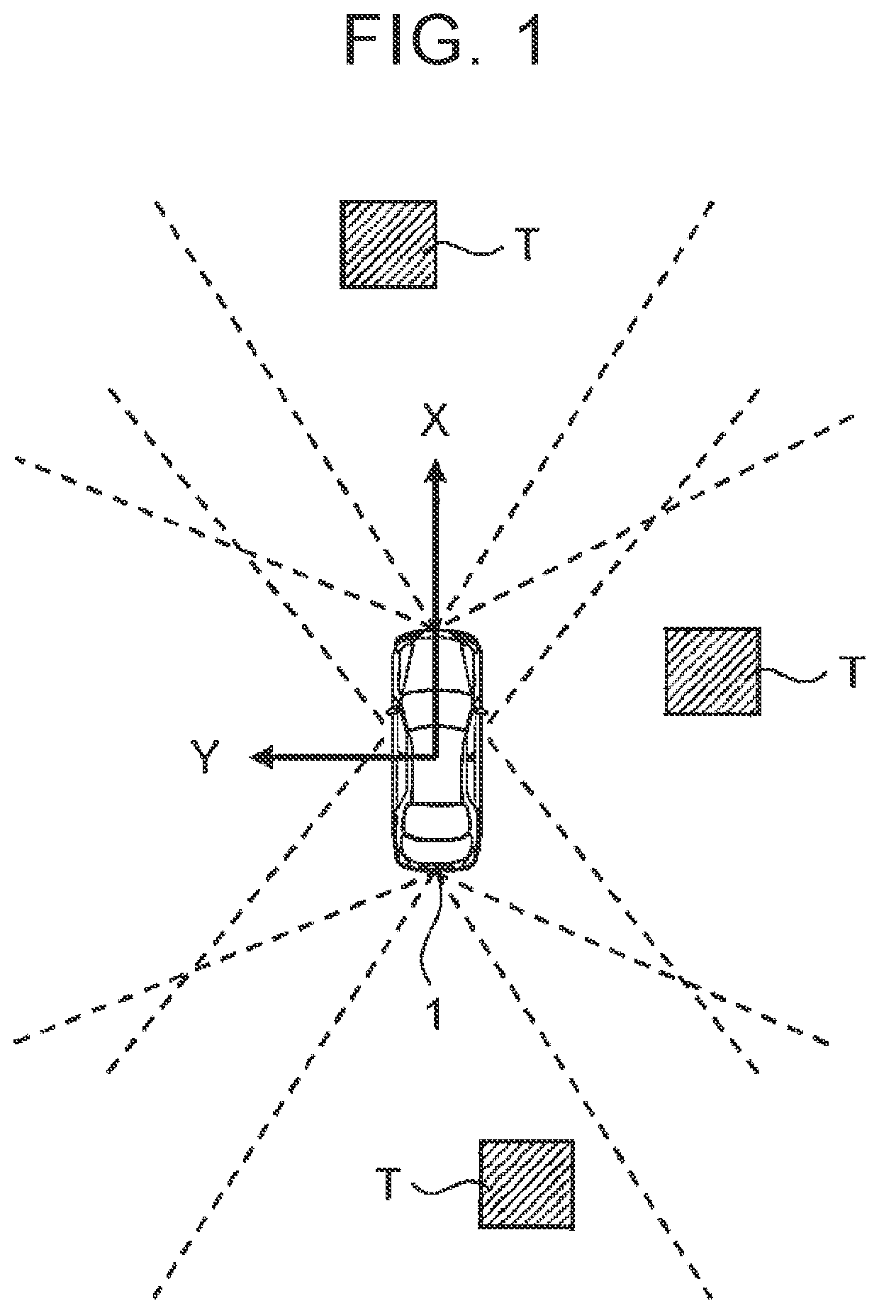
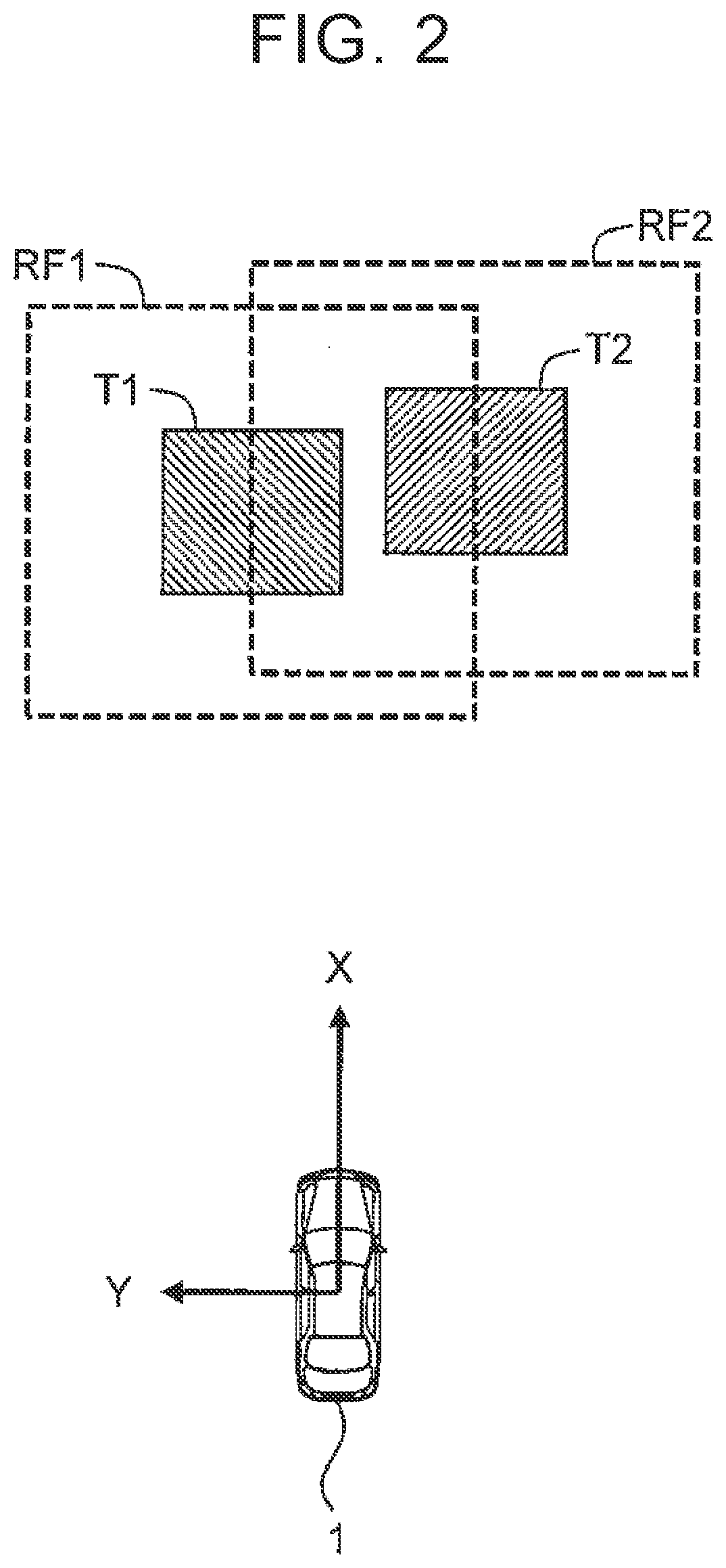
[0079]In step S210, the processor 110 initially sets the integration determination distance DF (integration determination range RF) for the detected object T. More specifically, the processor 110 refers to the object information 300 and, based on the detection position of the object T obtained by referring to the object information 300, initially sets the integration determination distance DF. The detection position used as the base is the base point. For example, the point nearest to the vehicle 1 is used as the base point. As another example, a point that is stably detected (tracked) over a certain period of time may be used as the base point. The initially set value of the integration determination distance DF may be set as a constant value or may be set according to the detection range of the object T.

[0080]In step S250, the processor 110 estimates the traveling direction P of the o...

second example

5-2. Second Example

[0082]FIG. 16 is a flowchart showing a second example of processing in step S200. A duplicate description of those steps included in the first example will be omitted as appropriate. Step S210 and step S250 are the same as those in the first example.

[0083]In step S220, the processor 110 calculates the absolute speed V of the object T based on the sensor detection information 200. The absolute speed V of the object T is calculated from the speed of the vehicle 1 and the relative speed of the object T. The speed of the vehicle 1 is obtained from the vehicle state information.

[0084]In the second example, step S260A is performed instead of step S260. In step S260A, the processor 110 increases the integration determination distance DF along the traveling direction P of the object T. At this time, the processor 110 increases the increase amount of the integration determination distance DF along the traveling direction P according to the absolute speed V of the object T....

third example

5-3. Third Example

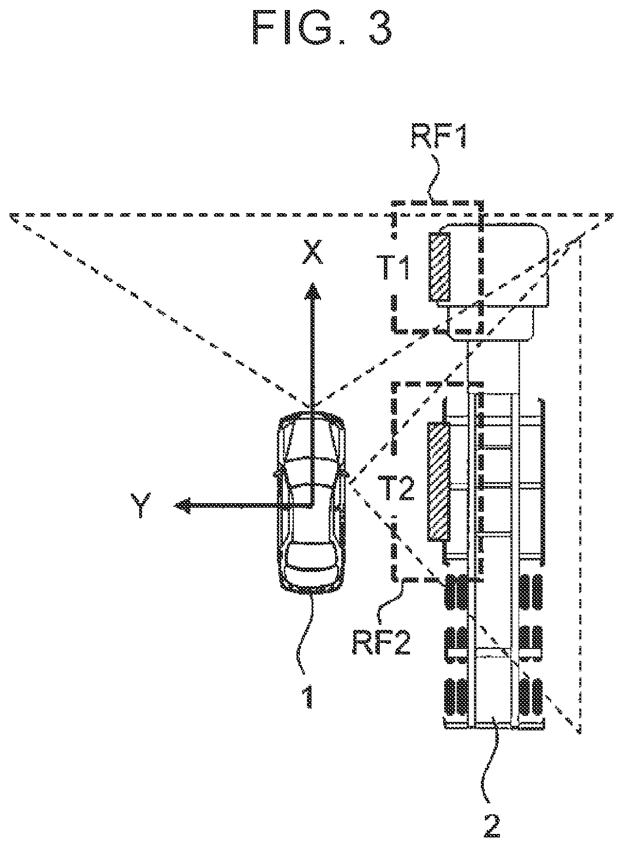
[0087]In the second example described above, the increase amount of the integration determination distance DF along the traveling direction P increases according to the absolute speed V of the object T. However, in some cases, the reliability of the calculated absolute speed V is low. For example, in FIG. 18, the object TX is located near the boundary of the field of view of the sensor. The reliability of the absolute speed V calculated (estimated) for such an object TX is low. When the integration determination distance DF is set based on the absolute speed V with low reliability, the accuracy of the integration determination distance DF is not increased but decreased. To address this problem, the setting method of the integration determination distance DF is changed in the third example according to the reliability of the absolute speed V.

[0088]FIG. 19 is a flowchart showing a third example of processing in step S200. A duplicate description of those steps includ...


PUM


Abstract

An object recognition device includes: a sensor; a storage device; and a processor configured to detect a first object and a second object around the vehicle, initially set, based on a detection position of the first object, an integration determination distance used to determine that the first object and the second object belong to the same object, estimate a traveling direction of the first object based on the sensor detection information, increase the integration determination distance along the traveling direction, after increasing the integration determination distance along the traveling direction, determine, based on the integration determination distance, whether the first object and the second object belong to the same object, and output the first object and the second object as the same object when it is determined that the first object and the second object belong to the same object.

Description

CROSS-REFERENCE TO RELATED APPLICATIONS[0001]This application claims priority to Japanese Patent Application No. 2018-151605 filed on Aug. 10, 2018, which is incorporated herein by reference in its entirety including the specification, drawings and abstract.BACKGROUND1. Technical Field[0002]The present disclosure relates to an object recognition device.2. Description of Related Art[0003]Japanese Patent Application Publication No. 2009-186276 (JP 2009-186276 A) discloses an object detection device mounted on a vehicle. The object detection device integrates a plurality of objects detected within a predetermined range and recognizes them as a single object. The predetermined range is a rectangular range with the front-rear width and the left-right width of the predetermined range variably set based on the absolute speed of the objects. In this case, the front-rear width of the predetermined range is increased along the traveling direction of the vehicle in which the object detection d...

Claims


Application Information

Patent Timeline
Patent Type & Authority Patents(United States)
IPC IPC(8): B60W30/09G05D1/02G01S17/931
CPCB60W30/09G05D1/0214B60W2554/801B60W2554/804G01S17/931G05D2201/0213G05D1/0248G01S13/931
Inventor KOMORI, TERUMOTO
Owner TOYOTA JIDOSHA KK
Why Eureka
Try Eureka