Liquid discharge head

a liquid discharge head and liquid discharge technology, applied in the direction of printing, inking apparatus, etc., can solve the problems of low degree of freedom in arranging inflow ports and discharge ports, complex configuration of flow channels connected to the common liquid chambers, etc., and achieve the effect of simplifying the configuration of flow channels

Active Publication Date: 2022-02-22
BROTHER KOGYO KK
View PDF9 Cites 0 Cited by
  • Summary
  • Abstract
  • Description
  • Claims
  • Application Information

AI Technical Summary

Benefits of technology

[0005]Thus, there is such a fear that the configurations of the flow channels connected to the common liquid chambers might be complex. Further, for example, for a purpose of avoiding any interference between the flow channels connected to the two inflow ports, any interference between the flow channels connected to the two discharge ports, and any interference between the flow channels connected to the two inflow ports and the flow channel connected to the two discharge ports, it is necessary that the inflow ports, the discharge ports, and the inflow ports and the discharge ports are arranged to be apart from one another to a certain extent. Therefore, in the above-described liquid jetting head having the two inflow ports and the two discharge ports, the degree of freedom in arranging the inflow ports and the discharge ports is low.
[0006]An object of the present disclosure is to provide a liquid discharge head which is capable of simplifying the configuration of flow channels connected to a common flow channel (common channel) and in which the degree of freedom in arranging a supply port and a discharge port provided on the common channel is high.

Problems solved by technology

Thus, there is such a fear that the configurations of the flow channels connected to the common liquid chambers might be complex.
Therefore, in the above-described liquid jetting head having the two inflow ports and the two discharge ports, the degree of freedom in arranging the inflow ports and the discharge ports is low.

Method used


Image

  • Liquid discharge head
  • Liquid discharge head
  • Liquid discharge head

Examples


Embodiment Construction

[0022]In the following, an embodiment of the present disclosure will be explained.

Overall Configuration of Printer 1

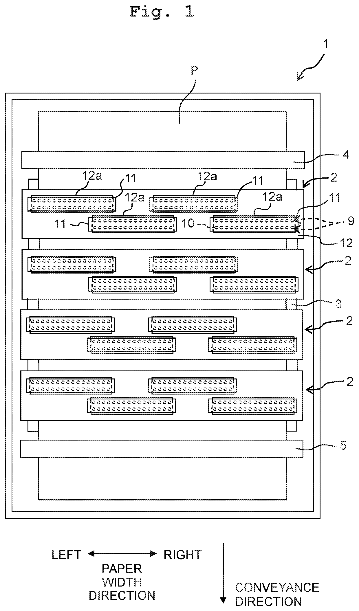
[0023]As depicted in FIG. 1, a printer 1 according to the present embodiment is provided with four ink-jet heads 2, a platen 3 and conveying rollers 4 and 5.

[0024]The four ink-jet heads 2 are arranged side by side in a conveyance direction (corresponding to a “second direction” of the present disclosure) which is horizontal and in which a recording paper sheet (recording paper) P is conveyed by the conveying rollers 4 and 5 as will be described later on; each of the four ink-jet heads 2 is provided with four head units 11 (corresponding to a “liquid discharge head” of the present disclosure), and a holding member 12. Each of the head units 11 discharges or jets an ink from a plurality of nozzles 10 formed in a lower surface thereof. Here, as the ink discharged from the plurality of nozzles 10 of the head unit 11, black, yellow, cyan and magenta inks are discharged, in ...


PUM


Abstract

A liquid discharge head includes: individual channel rows; a common channel; a supply port via which liquid is supplied to the common channel; and a discharge port via which the liquid is discharged from the common channel. Each of the individual channel rows is formed of individual channels aligned in a first direction, each of the individual channels includes a nozzle, and the individual channel rows are arranged in a second direction crossing the first direction. The common channel extends in the first direction, and extends in the second direction over an entire length of an area in which the individual channel rows are arranged. The common channel overlaps with the individual channel rows in a third direction orthogonal to both of the first and second directions, and communicates with the individual channels constructing each of the individual channel rows.

Description

CROSS REFERENCE TO RELATED APPLICATION[0001]The present application claims priority from Japanese Patent Application No. 2018-236573 filed on Dec. 18, 2018, the disclosure of which is incorporated herein by reference in its entirety.BACKGROUNDField of the Invention[0002]The present disclosure is related to a liquid discharge head which discharges liquid from nozzles.Description of the Related Art[0003]As a liquid discharge head which discharges liquid from nozzles, there is a known liquid jetting head which jets or discharges ink from nozzles. In this known liquid jetting head, two individual channel rows, each of which is formed by aligning individual flow channels (channels) including nozzles and pressure chambers in a Y direction, are arranged in a X direction. Further, common liquid chambers are arranged, respectively, at locations above the two individual channel rows. The ceiling surface of each of the common liquid chambers is provided with an inflow port arranged in one end ...

Claims


Application Information

Patent Timeline
Patent Type & Authority Patents(United States)
IPC IPC(8): B41J2/14B41J2/18B41J2/155
CPCB41J2/1433B41J2/155B41J2/18B41J2002/14241B41J2002/14419B41J2002/14459B41J2002/14491B41J2202/08B41J2202/12B41J2202/18B41J2/14233
Inventor HAYASHI, HIDEKI
Owner BROTHER KOGYO KK
Why Eureka
Try Eureka