Safety switching device with recessed setting components

a safety switching device and component technology, applied in the direction of printed circuit non-printed electric components, printed circuit aspects, electrical apparatus, etc., can solve the problems of not being able to provide the necessary stability, not being available, and difficult or impossible to replace the electrical components commonly used in safety switching devices by purely electronic elements, etc., to achieve comparable safety and stability, improve safety, and reduce the effect of housing width

Active Publication Date: 2022-04-05
PILZ (COMPANY)
View PDF12 Cites 0 Cited by
  • Summary
  • Abstract
  • Description
  • Claims
  • Application Information

AI Technical Summary

Benefits of technology

[0007]It is an object of the present disclosure to provide an improved safety switching device. In particular, it is an object to specify a safety switching device with a smaller size, in particular with a smaller housing width, which allows a comparable safety and stability as convention-al safety switching devices. Furthermore, it is an object to provide a safety switching device that can be produced with less manufacturing effort

Problems solved by technology

However, some electromechanical elements commonly used in safety switching devices are difficult or impossible to replace by purely electronic elements.
These elements are either not available, do not provide the necessary stability, or are not suitable for use in safety switching devices from a safety perspective.

Method used


Image

  • Safety switching device with recessed setting components
  • Safety switching device with recessed setting components
  • Safety switching device with recessed setting components

Examples


Embodiment Construction

[0046]In the following, the figures are explained in detail. The same reference signs denote the same parts in all drawings and are not explained in detail for each figure.

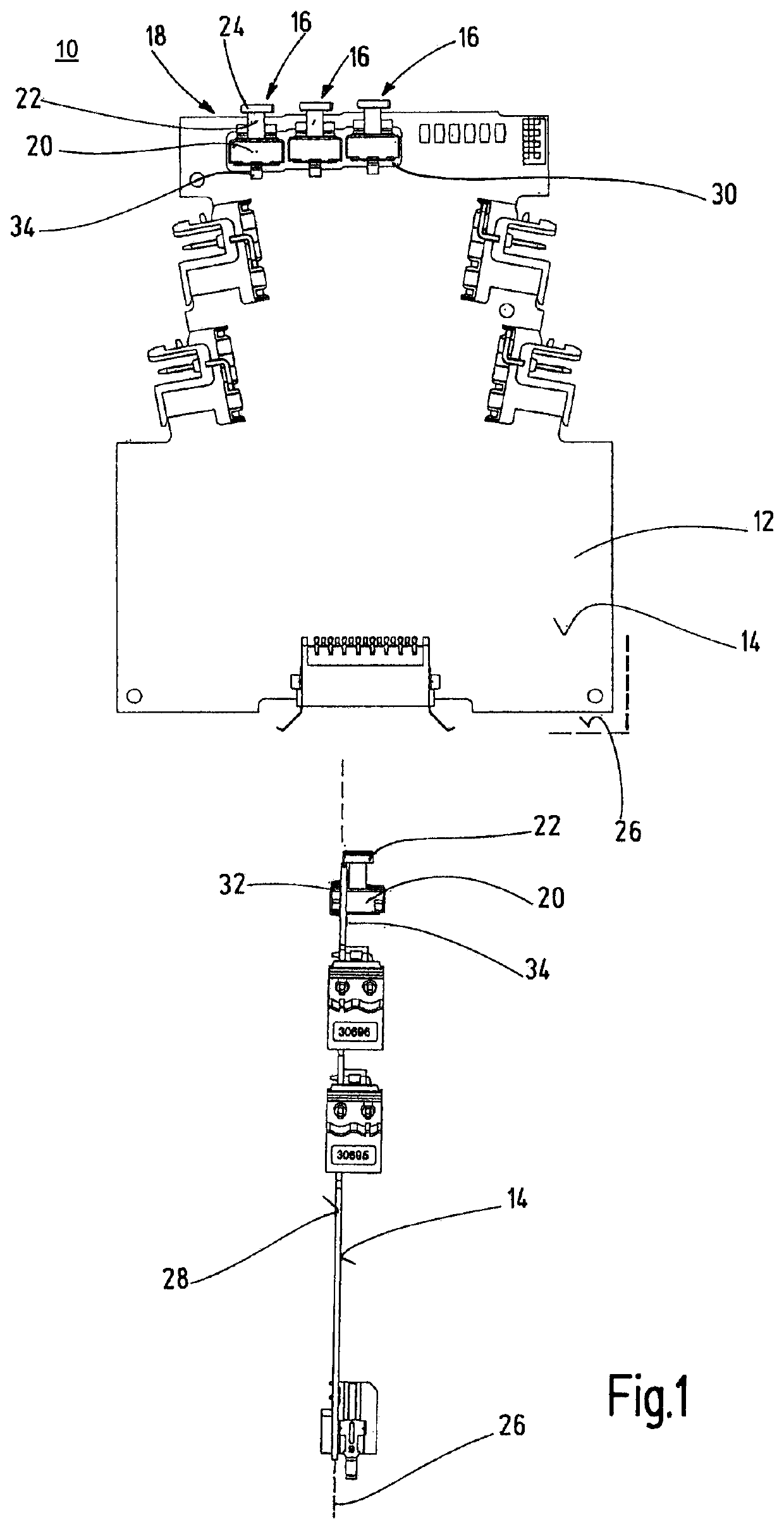
[0047]FIG. 1 shows a top view and a side view of a safety switching device according to an embodiment of this disclosure without an enclosing housing. In FIG. 1, the safety switching device according to an embodiment of the present disclosure is denoted in its entirety with the reference numeral 10.

[0048]The safety switching device comprises a printed circuit board 12, on whose surface 14 an electrical circuit is arranged. The electrical circuit performs the safety related function, i.e. for example, the switching on and safely off of the load, which is not described here in detail. The electrical circuit contains the elements essential for controlling a load and may in particular comprise one or more circuits including an evaluation unit, input and output circuits and several switching elements.

[0049]The electric...


PUM


Abstract

A safety switching device for controlling a load having at least one input for receiving an input signal and one output for outputting an output signal, and having an electrical circuit which provides the output signal as a function of the input signal. The electrical circuit is arranged on a printed circuit board and is coupled to at least one setting component for setting an operating parameter of the safety switching device. The surface of the printed circuit board defines a mounting plane, and the at least one setting component has an adjusting element in a housing and is arranged recessed on the printed circuit board so that the housing of the adjusting element intersects the mounting plane.

Description

CROSS-REFERENCE TO RELATED APPLICATION[0001]This application claims priority from German patent application DE 10 2018 115 243.4 filed on Jun. 25, 2018. The entire content of the priority application is incorporated herein by reference.BACKGROUND OF THE INVENTION[0002]The present disclosure relates to a safety switching device for controlling a load, in particular for switching the load on and safely off, with at least one input for receiving an input signal and one output for outputting an output signal, and with an electrical circuit which provides the output signal as a function of the input signal. Furthermore, the present disclosure relates to a setting component for adjusting an operating parameter of such a safety switching device as well as a method for manufacturing such a safety switching device.[0003]Safety switching devices of that type are mainly used in the industrial sector to switch electrically driven machines, such as a press or a milling tool, on and safely off. I...

Claims


Application Information

Patent Timeline
Patent Type & Authority Patents(United States)
IPC IPC(8): H01H19/14H05K1/18
CPCH01H19/14H05K1/182H05K2201/10053H03K17/9625H05K3/3421H05K2201/10196H01H71/74
Inventor ZINSER, CHRISTOPHMERZ, LOTHAR
Owner PILZ (COMPANY)
Why Eureka
Try Eureka