Hand crimp tool having wire inserter

a technology of inserter and crimping tool, which is applied in the direction of metal-working hand tools, line/current collector details, electrical equipment, etc., can solve the problems of improper crimping of terminals to wires, manufacturing assemblies,

Active Publication Date: 2022-04-05
TYCO ELECTRONICS LOGISTICS AG (CH)
View PDF5 Cites 2 Cited by
  • Summary
  • Abstract
  • Description
  • Claims
  • Application Information

AI Technical Summary

Benefits of technology

[0006]In one embodiment, a hand crimp tool is provided including a handle including an upper handle and a lower handle movable relative to each other to open and close the hand crimp tool. The upper handle includes an upper handgrip and the lower handle includes a lower handgrip. The upper handgrip and the lower handgrip are configured to be hand squeezed to close the hand crimp tool. The hand crimp tool includes a head having an upper jaw operably coupled to the upper handle and a lower jaw operably coupled to the lower handle. The head includes a crimp zone between the upper jaw and the lower jaw. The lower jaw includes an anvil configured to hold a terminal and the upper jaw includes a crimper configured to crimp the terminal between the anvil and the crimper when the hand crimp tool is closed. The hand crimp tool includes a terminal locator coupled to the head proximate to the anvil. The terminal locator has a terminal channel configured to receive the terminal oriented relative to the anvil. The terminal locator has a terminal lock configured to lock the terminal in the terminal channel. The hand crimp tool includes a wire inserter coupled to the head. The wire inserter includes a carriage movable between an advanced position and a retracted position. The wire inserter has a wire clamp holding a wire in the carriage and the wire inserter moves the wire relative to the head to position and hold the wire in the terminal during crimping of the terminal between the anvil and the crimper.

Problems solved by technology

However, the wire may be inconsistently positioned, leading to variations in the manufactured assemblies.
Additionally, if the wire is inserted with too little force, the terminal may be improperly crimped to the wire and may be inoperable leading to waste.

Method used


Image

  • Hand crimp tool having wire inserter
  • Hand crimp tool having wire inserter
  • Hand crimp tool having wire inserter

Examples


Embodiment Construction

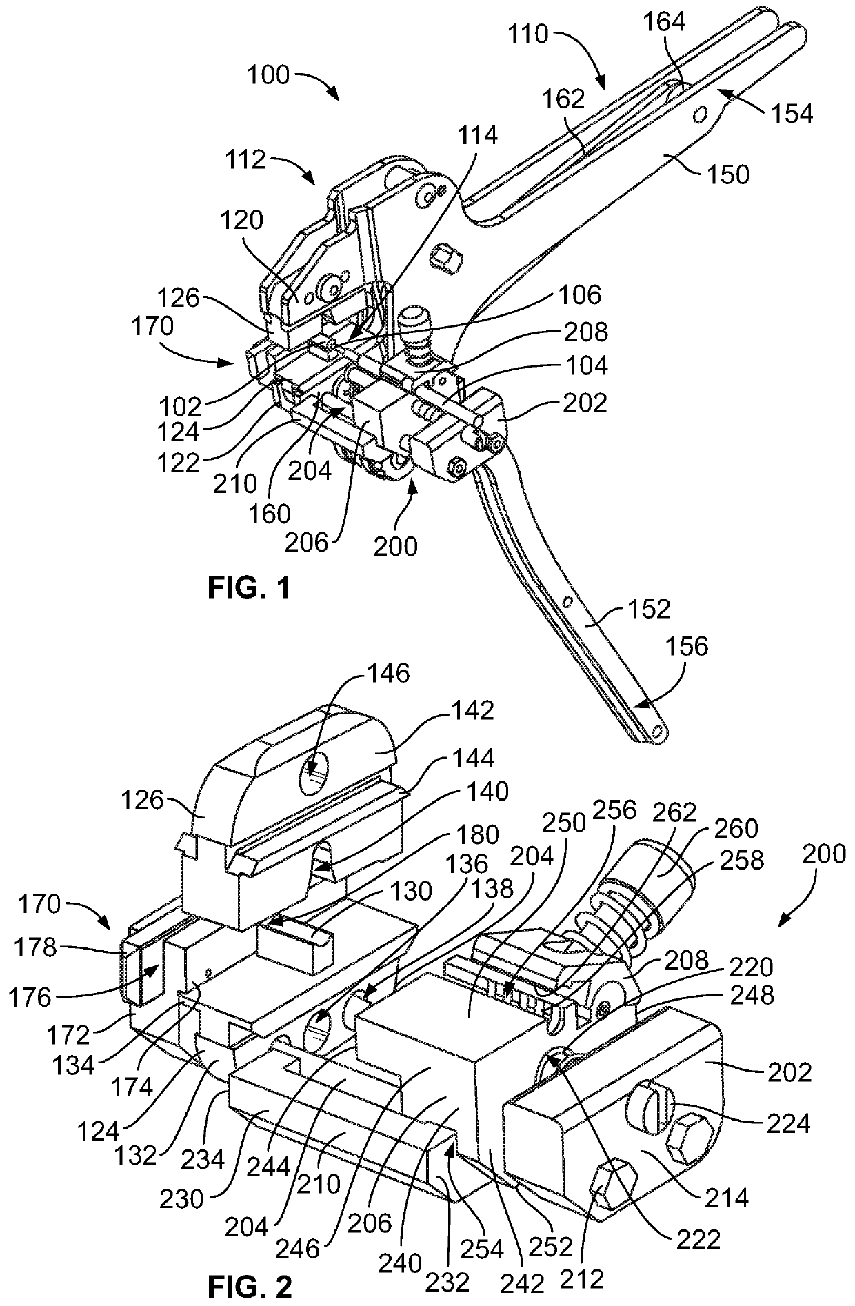
[0019]FIG. 1 is a perspective view of a hand crimp tool 100 in accordance with an exemplary embodiment. The hand crimp tool 100 is used for hand crimping a terminal 102 to a wire 104. For example, the hand crimp tool 100 may be opened and closed during a crimping process to crimp the terminal 102 to the wire 104. The hand crimp tool 100 is hand actuated by an operator to close the hand crimp tool 100 during the crimping process. In an exemplary embodiment, a contact 106 is provided at the end of the wire 104 and loaded into the terminal 102 with the wire 104. The terminal 102 is crimped to the wire 104 around the contact 106. For example, the contact 106 defines a center contact terminated to a center conductor of the wire 104 and the terminal 102 defines an outer contact terminated to a shield of the wire 104. In other various embodiments, the wire 104 is provided without the contact 106 and the terminal 102 is terminated to the center conductor of the wire 104.

[0020]The hand crimp...


PUM

PropertyMeasurementUnit
loading forceaaaaaaaaaa

Abstract

A hand crimp tool includes a handle having upper and lower handles having upper and lower handgrips hand squeezed to close the hand crimp tool. The hand crimp tool includes a head having upper and lower jaws defining a crimp zone therebetween. The lower jaw includes an anvil holding a terminal and the upper jaw includes a crimper crimping the terminal. The hand crimp tool includes a wire inserter coupled to the head having a carriage movable between an advanced position and a retracted position. The wire inserter has a wire clamp holding a wire in the carriage and the wire inserter moves the wire relative to the head to position and hold the wire in the terminal during crimping of the terminal between the anvil and the crimper.

Description

BACKGROUND OF THE INVENTION[0001]The subject matter herein relates generally to hand crimp tools.[0002]Crimping machines are used to crimp terminals to wires. Various crimping machines are electrically actuated using a motor to drive the crimper to crimp the terminal to the wire. Such machines use a device to automatically position the wire in the crimp zone by controlling the position of the end of the wire in the crimp zone. Other various crimping machines are hand tools used to crimp the terminal to the wire. Such hand tools are hand crimped by squeezing the tool by hand. The wire is typically held in one hand of the operator and the tool is squeezed by the operator's other hand. However, the wire may be inconsistently positioned, leading to variations in the manufactured assemblies. Additionally, if the wire is inserted with too little force, the terminal may be improperly crimped to the wire and may be inoperable leading to waste.[0003]A need remains for a hand crimp tool that ...

Claims


Application Information

Patent Timeline
Patent Type & Authority Patents(United States)
IPC IPC(8): H01R43/045H01R43/042
CPCH01R43/045H01R43/0421H01R43/042Y10T29/53226B25B27/146Y10T29/53235Y10T29/53257Y10T29/53222
Inventor KERSTETTER, CHADWICK ALANMOYER, CALEB ANDREW
Owner TYCO ELECTRONICS LOGISTICS AG (CH)
Why Eureka
Try Eureka