Wire bar, method of manufacturing wire bar, and image forming apparatus

a wire bar and wire bar technology, applied in the field of image forming technique, to achieve the effect of preventing deviation of wire wounds, stable scraping of liquids, and improving development accuracy

Inactive Publication Date: 2009-02-17
SEIKO EPSON CORP
View PDF9 Cites 2 Cited by
  • Summary
  • Abstract
  • Description
  • Claims
  • Application Information

AI Technical Summary

Benefits of technology

[0015]The invention has been made in light of these problems, and accordingly, a first object of the invention is to effectively prevent deviation of a wire wound around a rod-like member in a wire bar which is obtained by winding the wire around a peripheral surface of the rod-like member.
[0016]A second object of the invention is to provide a wire bar which achieves stable scraping off a liquid with a regulator member and provide a method of manufacturing this wire bar.
[0017]A third object of the invention is to provide a technique which always secures favorable contact of a wire bar at a coating position with a developing agent carrier by preventing loosening of a wire wound around the wire bar.
[0018]A fourth object of the invention is to provide an image forming apparatus which prevents a coated pattern of a liquid developing agent applied by a wire bar to a developing agent carrier from getting disturbed, and which accordingly improves the accuracy of development.

Problems solved by technology

However, an apparatus structured as such sometimes causes the following problems.

Method used


Image

  • Wire bar, method of manufacturing wire bar, and image forming apparatus
  • Wire bar, method of manufacturing wire bar, and image forming apparatus
  • Wire bar, method of manufacturing wire bar, and image forming apparatus

Examples


first embodiment

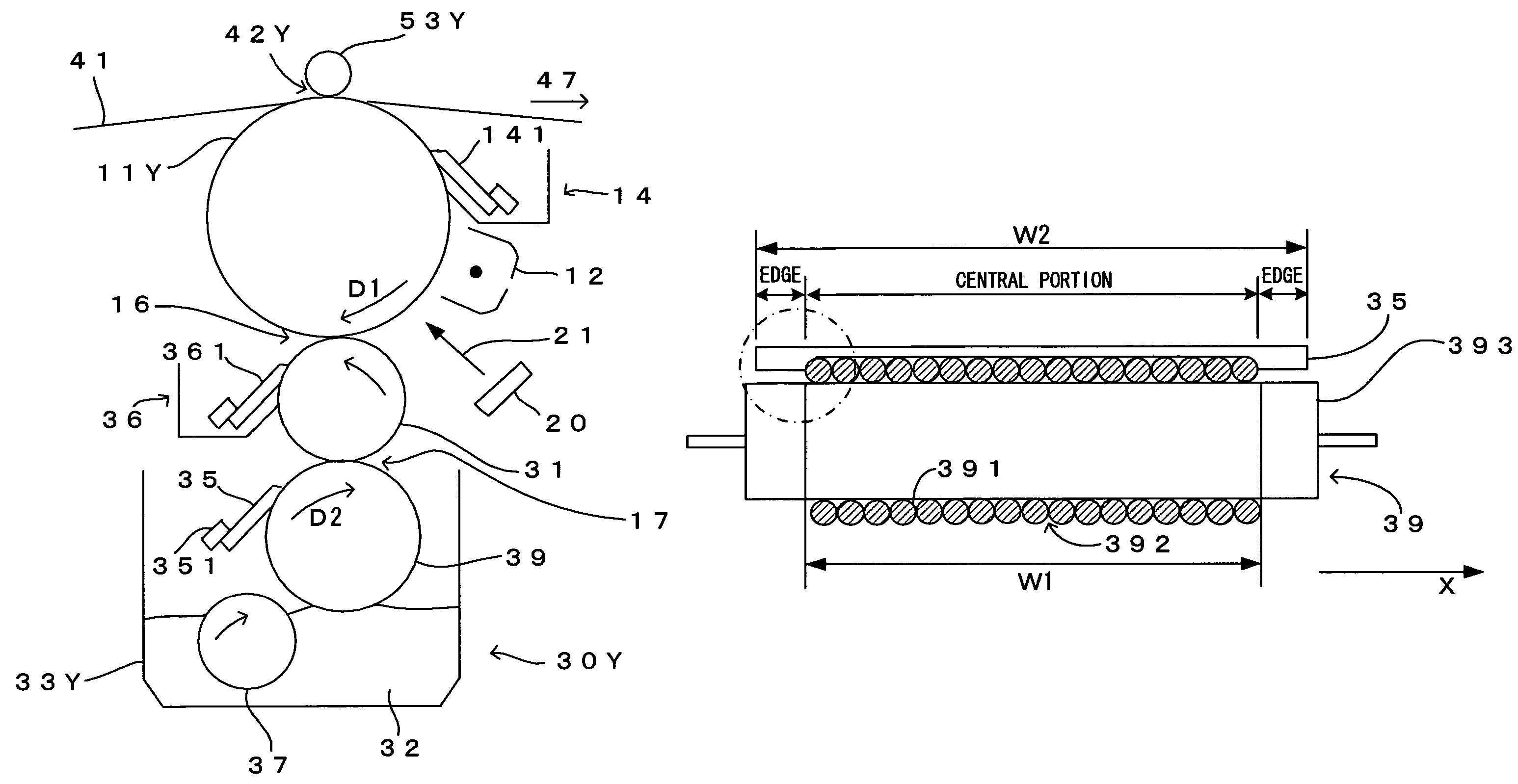
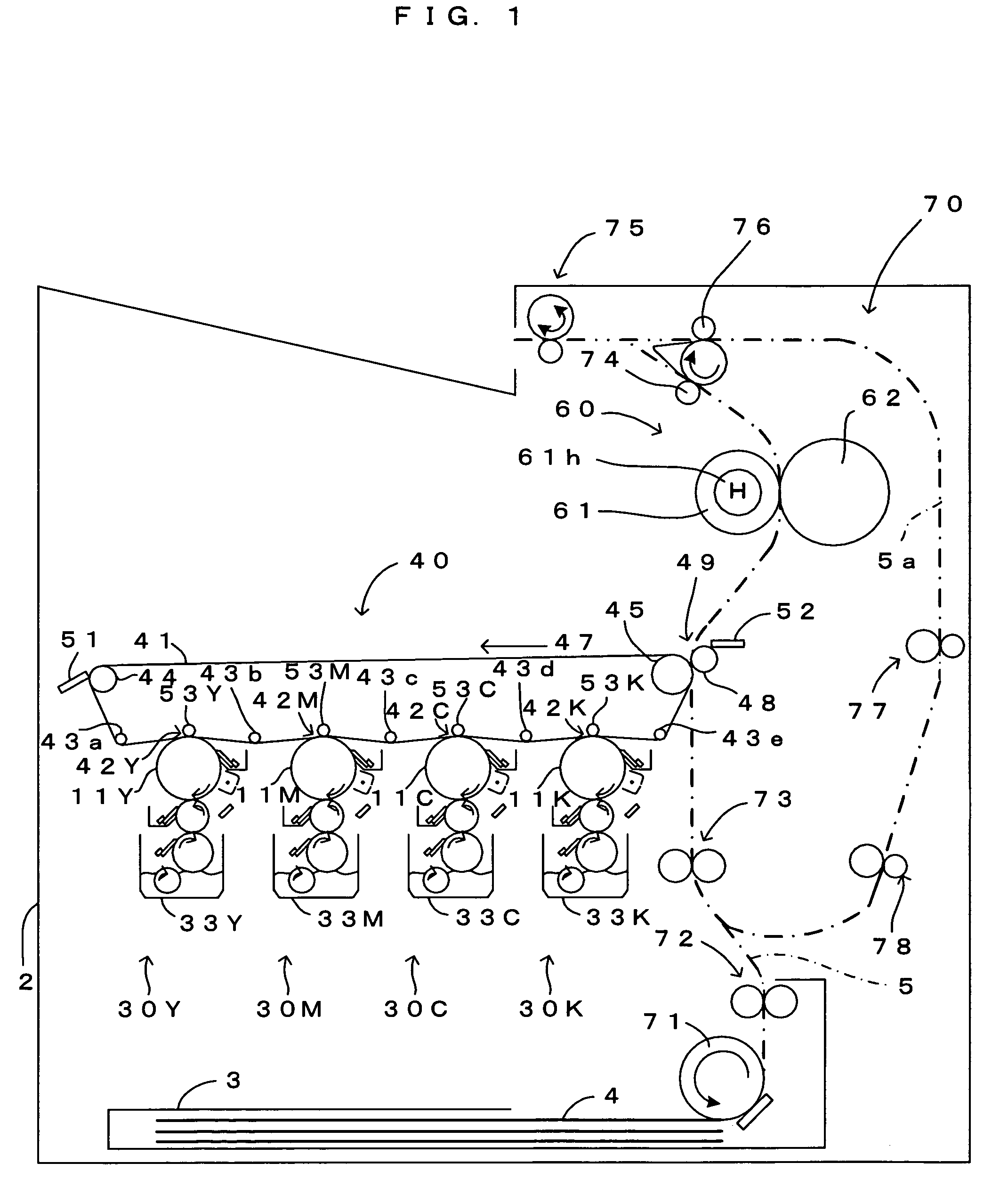
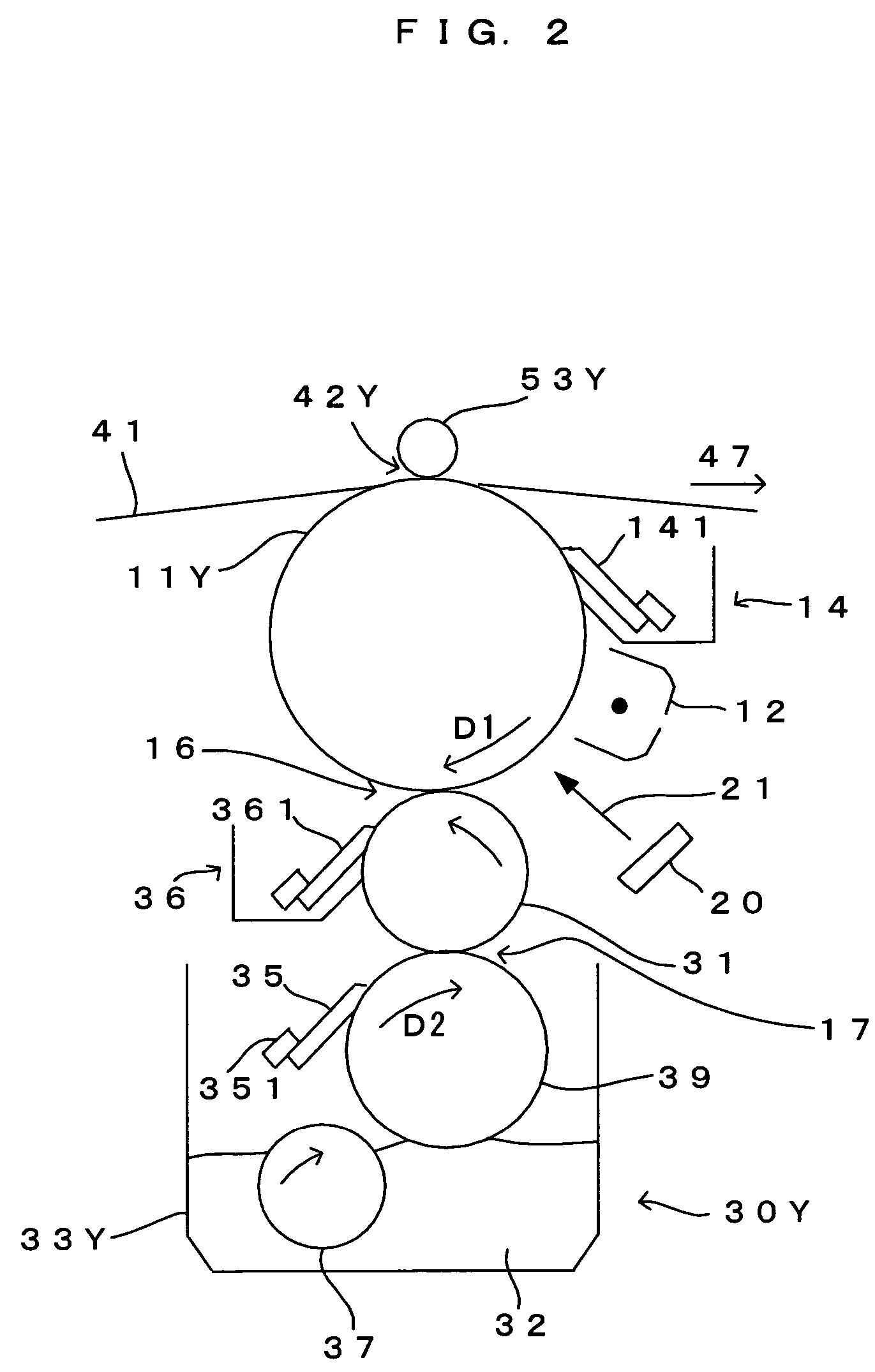
[0050]FIG. 1 is a drawing which shows the internal structure of a printer, a first embodiment of an image forming apparatus according to the invention. FIG. 2 is an enlarged view of an essential part in FIG. 1, and FIG. 3 is a block diagram which shows the electric structure of the printer. This image forming apparatus is a color printer of the so-called tandem type, and photosensitive members 11Y, 11M, 11C and 11K for the four colors of yellow (Y), magenta (M), cyan (C) and black (K) are disposed as the “latent image carrier” of the invention parallel to each other inside a main apparatus section 2. A liquid development method is implemented in this printer, to thereby superimpose toner images carried on the photosensitive members 11Y, 11M, 11C and 11K upon each other and form a full color image, or form a monochrome image using a black (K) toner image alone. In this printer, as a print command signal containing an image signal is fed to a main controller 100 from an external appar...

second embodiment

[0086]FIG. 8 is an enlarged schematic diagram of a wire bar and a regulator blade in the second embodiment of the image forming apparatus according to the invention. A major difference of the second embodiment from the first embodiment is that concaves 353 corresponding to the coating area are formed in a central portion of a regulator blade 35b, and other structures are similar to those in the first embodiment. The second embodiment will now be described in detail, focusing mainly on the difference from the first embodiment. The structures and the operations which are the same as those according to the first embodiment will not be described.

[0087]The regulator blade 35b according to the second embodiment is made of urethane rubber which serves as an elastic member. There are the concaves 353 in the central portion of the regulator blade 35b and there are steps HK at the boundaries between the ends and the central portion of the regulator blade 35b. The regulator blade 35b is dispos...

third embodiment

[0088]FIG. 9 is an enlarged schematic diagram of a wire bar and a regulator blade in the third embodiment of the image forming apparatus according to the invention. A major difference of the third embodiment from the first embodiment is that the width W2 of a regulator blade 35c is wider than the width W3 of the wire bar 39, and other structures are similar to those in the first embodiment. The third embodiment will now be described in detail, focusing mainly on the difference from the first embodiment. The structures and the operations which are the same as those according to the first embodiment will not be described.

[0089]In the third embodiment, along the X-direction, the width W2 of the regulator blade 35c is wider than the width W3 of the wire bar 39 (metal core 393), and the both edges of the regulator blade 35c are respectively located on the outer side to the both edges of the wire bar 39 (metal core 393). Since the both edges of the regulator blade 35 are respectively loca...


PUM

PropertyMeasurementUnit
contact angleaaaaaaaaaa
diameteraaaaaaaaaa
diameteraaaaaaaaaa

Abstract

A wire bar is formed by winding a wire, which comprises a first flat portion formed along an overall longitudinal length, around a peripheral surface of a metal core such that the peripheral surface of the metal core and the first flat portion tightly contact with each other. Since this increases the area size of a contact portion where the wire and the metal core contact each other, it is possible to increase the force of static friction which fixes the wire to the metal core. Fixing of the wound wire to the metal core by the strong force of static friction effectively prevents the wound wire from getting deviated.

Description

CROSS REFERENCE TO RELATED APPLICATION[0001]The disclosure of Japanese Patent Applications enumerated below including specification, drawings and claims is incorporated herein by reference in its entirety:[0002]No. 2004-236499 filed Aug. 16, 2004;[0003]No. 2004-331445 filed Nov. 16, 2004; and[0004]No. 2004-333983 filed Nov. 18, 2004.BACKGROUND OF THE INVENTION[0005]1. Field of the Invention[0006]The present invention relates to an image forming technique of the electrophotographic type for a printer, a copier machine, a facsimile machine and the like, and more particularly, to an image forming technique which uses liquid development as a development method.[0007]2. Description of the Related Art[0008]Known as a conventional image forming apparatus utilizing liquid development is a structure in which an electrostatic latent image formed on a photosensitive member (latent image carrier) is developed with a liquid developing agent which is evenly applied in a constant thickness to a su...

Claims


Application Information

Patent Timeline
Patent Type & Authority Patents(United States)
IPC IPC(8): G03G15/10
CPCG03G15/104Y10T29/51G03G2215/0658G03G2215/0629
Inventor KAMIJO, KOICHITAKANO, HIDEHIROIKUMA, KEN
Owner SEIKO EPSON CORP
Why Eureka
Try Eureka