Selectively reconfigurable drive-assembly

a drive assembly and reconfigurable technology, applied in the direction of steering parts, steering linkages, deflectable wheel steering, etc., can solve the problems of complex drive arrangement, difficult control, and inability to enable the autonomous robot to drive sideways

Active Publication Date: 2022-04-12
JOANNEUM RES FORSCHUNGS GMBH
View PDF3 Cites 0 Cited by
  • Summary
  • Abstract
  • Description
  • Claims
  • Application Information

AI Technical Summary

Benefits of technology

[0004]The above defined selectively reconfigurable drive assembly is based on the finding that by coupling the first and second wheels, only one steering actuator is necessary to perform the task of synchronously reconfiguring, both in time and angle, the rotations of the first and second wheels around the first and the second pivot axis respectively, i.e. to control a respective orientation of the first and the second wheel. Such a drive assembly extents the functionality of a differential-drive by allowing selective reconfiguration of the wheels, whilst providing a simple and robust steering mechanism. In other words: A selectively reconfigurable differential-drive assembly is provided. Furthermore, the capability to reconfigure the drive provides a fault-tolerant mode of operation. For example, one of the first and second wheels may be under-actuated or even free spinning. In this case, the drive can exhibit a controlled sideways movement by utilizing the operational wheel and the steering actuator only.
[0006]Thus, the drive assembly allows for circular or sideward movements of a vehicle driven by the drive assembly without applying different angular velocities to the first and second wheels. Accordingly, the drive assembly enables the vehicle to perform agile movements in a confined driving area.
[0007]According to another embodiment, the first adjustment angle equals the second adjustment angle. In that manner, the drive assembly is enabled to precisely change the direction of a translational movement without the need of performing rotational movements. Furthermore, the orientation of the wheels can be reconfigured during a translational movement of the vehicle. For example, the orientation of the wheels can be changed without interrupting a purely translational movement of the vehicle.
[0008]According to another embodiment, the second adjustment angle is a function, in particular a linear function of the first adjustment angle. Thus, the second adjustment angle equals, for example, the sum of the first adjustment angle and an offset, the offset being dependent on the first adjustment angle. That is, the absolute values of the first and second adjustment angles may differ. For example, the first and second wheels may be rotated in the same direction but with different adjustment angles. Thereby, the drive assembly is configured to perform a greater variety of circular movements. In particular, the drive assembly is enabled to more precisely determine a rotational movement through guaranteeing a controlled centre of rotation at a finite distance from the drive assembly.
[0010]Thereby, the drive assembly is enabled to adapt to specific mobility requirements. That is, in the first mode, the drive assembly allows for a steered circular movement by utilizing a common angular velocity of both wheels, and, in the second mode, the drive assembly allows for precise adjustments of the direction of a translational movement without changing the angular velocities of the wheels and without interrupting the translational movement.
[0012]Thereby, the drive assembly is configured to reset the first and the second wheel in their respective initial rotational position, i.e. their initial orientation in a differential-drive configuration, in case of a failure of the steering actuator of the drive assembly. In this case, the restoring means reset the first and second wheels in an initial position to perform standard differential-drive movements. Thus, the drive assembly is still enabled to move, using the remaining functional wheels, thereby providing a further fault-tolerant operation of the vehicle.

Problems solved by technology

Conventional differential-drives, however, do not enable the autonomous robot to drive sideways.
This type of maneuver can be difficult to execute, in particular when the robot has to operate in confined spaces, which becomes highly relevant whenever the robot has to deliver an object close to a handling position, for example.
These approaches, however, require a plurality of actuators, motors or stability mechanisms which results in a complex drive arrangement that is cost intensive and difficult to control whilst being less robust during operation.

Method used


Image

  • Selectively reconfigurable drive-assembly
  • Selectively reconfigurable drive-assembly
  • Selectively reconfigurable drive-assembly

Examples


Embodiment Construction

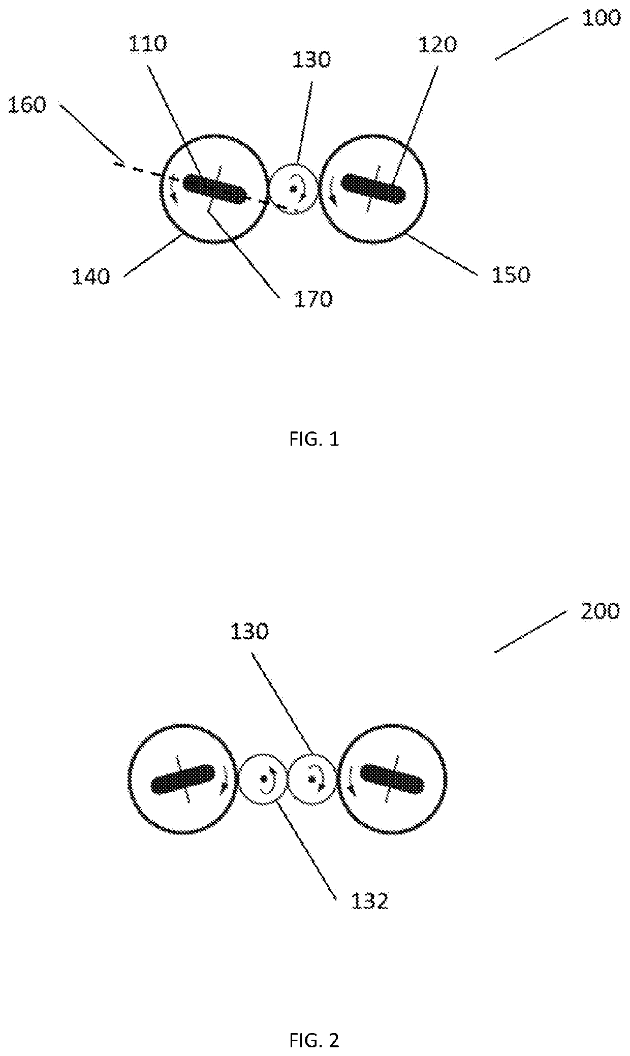
[0024]FIG. 1 shows a drive assembly 100 in a first operation mode, the drive assembly 100 comprising a first wheel 110, a second wheel 120 and a steering actuator 130. The first and second wheels 110 and 120 are arranged on rotatable platforms 140 and 150 respectively. The rotatable platforms 140 and 150 are rotatable around respective steering axes, e.g. first and second pivot axes that may coincide with the central axes of the rotatable platforms 140 and 150. The steering actuator 130 is coupled to the first and second rotatable platforms 140 and 150 or to the first and second pivot axes. The steering actuator 130 may be mechanically, hydraulically, electrically or magnetically coupled to the rotatable platforms 140 and 150 or to the first and second pivot axes. The mechanical coupling may be realised using gears or pull cables.

[0025]A rotation of the rotatable platforms 140 and 150 results in a rotation of the wheels 110 and 120 around the first and second pivot axis respectively...


PUM


Abstract

There is provided a drive assembly comprising: a reconfigurable differential drive comprising a first wheel and a second wheel, wherein the first and second wheels are moveable with different angular velocities around respective first and second rotation axes; a steering actuator configured to rotate the first wheel around a first pivot axis and / or the second wheel around a second pivot axis; wherein the first and second wheels are coupled such that a rotation of the first wheel around the first pivot axis by a first adjustment angle results in a rotation of the second wheel around the second pivot axis by a second adjustment angle, the second adjustment angle being dependent on the first adjustment angle.

Description

BACKGROUND OF THE INVENTION[0001]Mobile robots are used for a wide range of applications, such as for logistic purposes. The drives of such robots require high flexibility with respect to possible movements of the robot whilst being very robust in terms of their operation. A so-called differential-drive, wherein two parallel wheels share a common axis represents a configuration that allows a robot to perform translational or circular movements depending on rotational velocities applied to its wheels whilst being very simple in terms of its mechanical structure. Conventional differential-drives, however, do not enable the autonomous robot to drive sideways. In order to imitate a sideways movement, the robot needs to perform a hybrid maneuver that combines a sequence of rotational movements and translational forward movements. This type of maneuver can be difficult to execute, in particular when the robot has to operate in confined spaces, which becomes highly relevant whenever the ro...

Claims


Application Information

Patent Timeline
Patent Type & Authority Patents(United States)
IPC IPC(8): B62D9/00B62D9/04
CPCB62D9/002B62D9/04B62D7/1509B62D7/026
Inventor HOFBAUR, MICHAELBRANDSTÖTTER, MATHIAS
Owner JOANNEUM RES FORSCHUNGS GMBH
Why Eureka
Try Eureka