Wire harness routing apparatus
a wire harness and routing apparatus technology, applied in the direction of transportation and packaging, movable seats, cable arrangements between relatively moving parts, etc., can solve the problems of inability to increase the size of the wire harness cannot be accommodated in the rotation absorption case, and the wire harness cannot be installed
- Summary
- Abstract
- Description
- Claims
- Application Information
AI Technical Summary
Benefits of technology
Problems solved by technology
Method used
Image

Examples
first embodiment
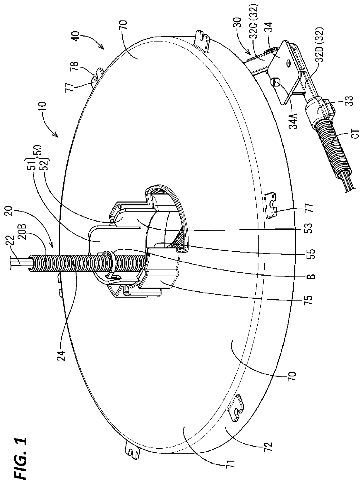
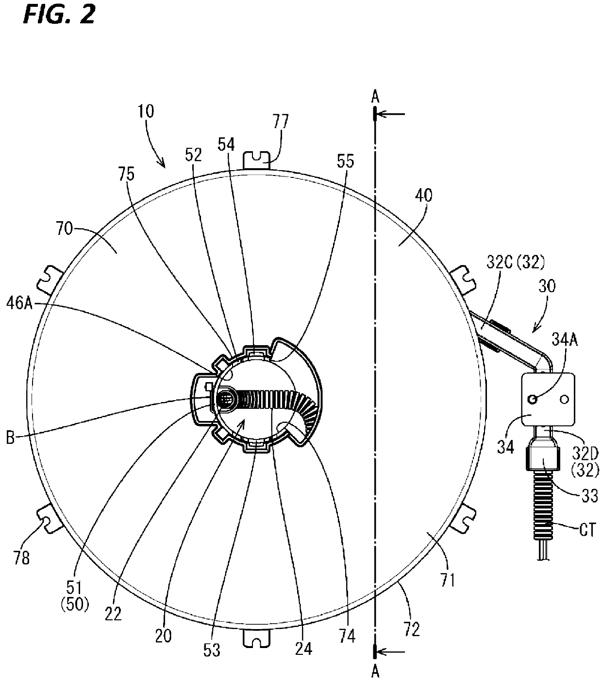
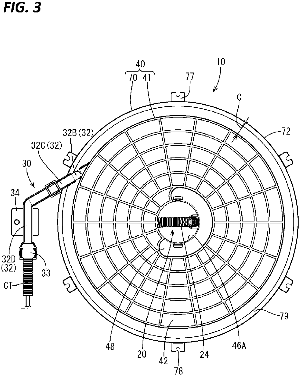
[0056]A first embodiment of the technique disclosed in the present specification will be described with reference to FIGS. 1 to 25.
[0057]As shown in FIG. 11, the present embodiment illustrates a wire harness routing apparatus 10 having a wire harness 20 that is routed between a seat S and a base portion 90 provided in a vehicle such as an automobile. Note that in the following description, the front-rear direction is described with reference to the directions of the arrows in the drawings, the F side being the front side, and the R side being the rear side.
[0058]The seat S is, for example, a seat on a driver's seat side of a vehicle, and as shown in FIGS. 16, 18, 20, 22, and 24, is fixed to a base portion 90 that can slide in a front-rear direction on a pair of metal rails 96 that are fixed to a floor portion of the vehicle.
[0059]As shown in FIGS. 10 to 15, the base portion 90 includes a base main body 92 that has an approximately circular frame shape and a pair of leg portions 94 t...
second embodiment
[0125]Next, a second embodiment will be described with reference to FIGS. 26 to 29.
[0126]As shown in FIGS. 26 and 27, in a wire harness 120 in a wire harness routing apparatus 110 of the second embodiment, an elastic wire material 128 is inserted together with the multiple wires 22 through the outer covering body 24 of the first embodiment, and since the configurations, operations, and effects that are in common with those of the first embodiment are redundant, description thereof will be omitted. Also, configurations that are the same as those of the first embodiment use the same reference numerals thereas.
[0127]The elastic wire material 128 of the second embodiment is a wire material that has rigidity according to which deformation can be performed in an arc shape, and for example, is made of piano wire, or the like. Also, the elastic wire material 128 is configured to be slightly longer than the entire length of the outer covering body 24, and when the elastic wire material 128 i...
third embodiment
[0132]Next, a third embodiment will be described with reference to FIGS. 30 to 32.
[0133]A wire harness 220 of a wire harness routing apparatus 210 of the third embodiment is obtained by modifying the shape of the outer covering body 24 of the first embodiment, and configurations, operations, and effects that are in common with those of the first embodiment are redundant, and therefore description thereof will be omitted. Also, configurations that are the same as those of the first embodiment use the same reference numerals thereas.
[0134]An outer covering body 224 of the wire harness 220 of the third embodiment is made of an insulating synthetic resin, and can be bent in only one direction with the multiple wires 22 inserted therein.
[0135]In the present embodiment, as shown in FIGS. 30 to 32, only portions on one side of approximately rectangular square tubes portion 224A are joined in the outer covering body 224, and thus the outer covering body 224 can be bent in only the rightward...
PUM
 Abstract
Description
Claims
Application Information
 - R&D
- Intellectual Property
- Life Sciences
- Materials
- Tech Scout
- Unparalleled Data Quality
- Higher Quality Content
- 60% Fewer Hallucinations
Browse by: Latest US Patents, China's latest patents, Technical Efficacy Thesaurus, Application Domain, Technology Topic, Popular Technical Reports.
© 2025 PatSnap. All rights reserved.Legal|Privacy policy|Modern Slavery Act Transparency Statement|Sitemap|About US| Contact US: help@patsnap.com