
Detachable radio frequency identification switch tag

a radio frequency identification and switch tag technology, applied in the direction of instruments, independent non-interfering antenna combinations, radiating element structural forms, etc., can solve the problem that the construction of a conventional rfid tag has limited flexibility to support operation in multiple frequencies

Active Publication Date: 2022-05-17
NEOLOGY INC
View PDF78 Cites 0 Cited by
  • Summary
  • Abstract
  • Description
  • Claims
  • Application Information

AI Technical Summary

Benefits of technology

The RFID switch tag can seamlessly transition between UHF and HF modes, enhancing its operational range and versatility in applications like electronic toll collection for high and single occupancy vehicle lanes, thereby expanding its utility across different frequency-based applications.

Problems solved by technology

However, the construction of a conventional RFID tag has limited flexibility to support operation in multiple frequencies.

Method used


Image

  • Detachable radio frequency identification switch tag
  • Detachable radio frequency identification switch tag
  • Detachable radio frequency identification switch tag

Examples


Embodiment Construction

[0019]While certain embodiments are described, these embodiments are presented by way of example only, and are not intended to limit the scope of protection. The methods and systems described herein may be embodied in a variety of other forms. Furthermore, various omissions, substitutions, and changes in the form of the example methods and systems described herein may be made without departing from the scope of protection.

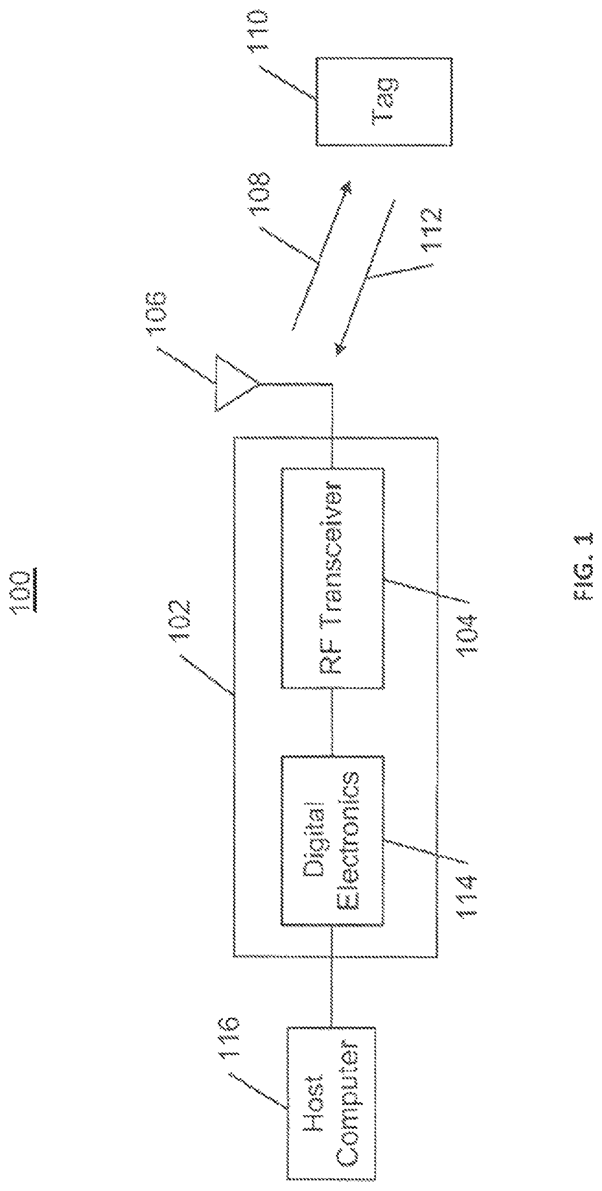
[0020]Embodiments described herein provide various designs of a radio frequency identification (RFID) tag which includes at least one base component and a detachable component such that the RFID tag can be configured in multiple configurations to support operations in multiple frequencies. In one aspect, a radio frequency identification (RFID) switch tag is disclosed. This RFID switch tag includes a base component having an ultra-high frequency (UHF) booster, such as an UHF booster antenna, and a detachable component having at least one UHF RFID module and a high f...


PUM


Abstract

A radio frequency identification (RFID) switch tag is disclosed. This RFID switch tag includes a base component having an ultra-high frequency (UHF) booster, and a detachable component having at least one UHF RFID module and a high frequency (HF) RFID module. In some embodiments, the detachable component is positioned in close proximity to the base component in a first configuration of the RFID switch tag such that the at least one UHF RFID module is sufficiently coupled to the UHF booster in the base component to form an UHF RFID system having a desired performance. The detachable component can also be separated from the base component to obtain a second configuration of the RFID switch tag, and the HF RFID module remains functional within the detached detachable component so that the detachable component can be used as a standalone HF RFID tag.

Description

RELATED APPLICATION INFORMATION[0001]This patent application is a continuation of application of U.S. application Ser. No. 16 / 677,663, filed Nov. 7, 2019, entitled “Detachable Radio Frequency Identification Switch Tag,” which claims the benefit under 35 U.S.C. § 119 (e) to U.S. Provisional Application No. 62 / 757,018, filed Nov. 7, 2018, and is a Continuation-in-Part of U.S. Non-Provisional application Ser. No. 16 / 384,643, filed Apr. 15, 2019, which is a continuation application of U.S. application Ser. No. 15 / 996,345, filed Jun. 1, 2018, now U.S. Pat. No. 10,262,253 issued on Apr. 16, 2016, entitled “RFID Switch Tag,”, which, in turn, is a continuation application of U.S. application Ser. No. 15 / 705,198, entitled “RFID Switch Tag,” filed Sep. 14, 2017, now U.S. Pat. No. 10,147,034 issued on Dec. 4, 2018, which is a continuation application of U.S. application Ser. No. 15 / 445,731, entitled “RFID Switch Tag,” filed Feb. 28, 2017, now U.S. Pat. No. 9,767,404, issued on Sep. 19, 2017, w...

Claims


Application Information

Patent Timeline
Patent Type & Authority Patents(United States)
IPC IPC(8): G06K19/077G06K19/04H01Q1/22G06K19/073
CPCG06K19/07715G06K19/041G06K19/07345G06K19/07701G06K19/07703G06K19/07745G06K19/07754G06K19/07773G06K19/07794H01Q1/2225H01Q7/00H01Q1/38H01Q21/28
Inventor NYALAMADUGU, SHESHIMULLIS, JOE
Owner NEOLOGY INC
Learn More