Determining the location of a mobile device

a mobile device and location technology, applied in the direction of image enhancement, process and machine control, instruments, etc., can solve the problems of not being able to estimate scale, i.e. actual distance travelled, and require very precise camera calibration, etc., to achieve the effect of maximising correlation and maximising correlation

Active Publication Date: 2022-05-31
OXFORD UNIV INNOVATION LTD
View PDF32 Cites 0 Cited by
  • Summary
  • Abstract
  • Description
  • Claims
  • Application Information

AI Technical Summary

Benefits of technology

[0026]Advantageously, the method further comprises the step of training the first, second and third neural networks to maximise the correlation between the features determined by the first neural network and the features determined by the second neural network. As the features of the first neural network and the second neural network are both indicative of the motion of the mobile device, in general correlation between the features should be expected, and so training to maximise such correlation is advantageous.

Problems solved by technology

However, such systems tend to require very precise calibration of the camera if location is to be reliably determined.
Such techniques tend to require precise camera calibration, and often fail in texture-poor environments (i.e. where there are with few features) or when a camera capturing images is rotated rapidly.
In addition, while such systems are usually able to determine the shape of a path of travel, they are usually unable to estimate scale, i.e. the actual distance travelled.
However, there are various problems with known systems that use neural networks.
They tend to require training for the specific environments in which they will be used, so cannot be used in new environments without suitable training occurring first.
However, there are various problems with known approaches using neural networks.
Disadvantageously, they require the camera data to be processed using traditional methods to obtain accurate pose estimates, and need markers to operate.
Furthermore, they cannot be trained end-to-end using raw data as input.
However, a problem with such systems is the image data and motion data needs to be time-synchronised, making such systems difficult to set up, as inertial sensors are not designed to provide motion data at the same intervals as cameras capture images.
Further, any miscalibration of the camera or inertial sensors can lead to significant errors.

Method used


Image

  • Determining the location of a mobile device
  • Determining the location of a mobile device
  • Determining the location of a mobile device

Examples


Embodiment Construction

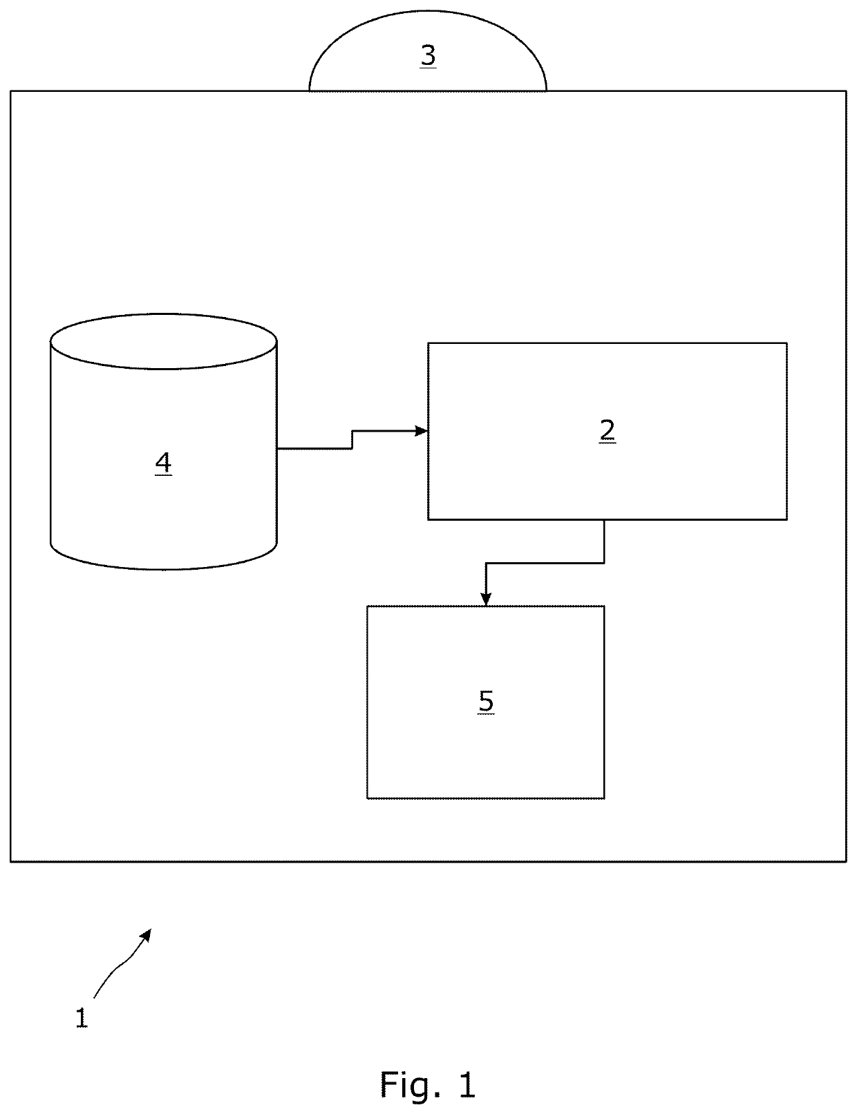
[0056]A schematic diagram of an autonomous robot in accordance with an embodiment of the invention is shown in FIG. 1. The autonomous robot 1 comprises a processor 2. It will be appreciated that in different embodiments the processor 2 may be a single processor system, a dual processor system, or any other suitable processor system. The processor 2 is in communication with a camera 3, a inertial sensor 5, and a memory 4 which stores (amongst other things) images captured by the camera 3 and motion data captured by the inertial sensor 5.

[0057]The inertial sensor 5 may be a gyroscope, accelerometer, magnetometer or any other suitable inertial sensor, or indeed a combination of such devices.

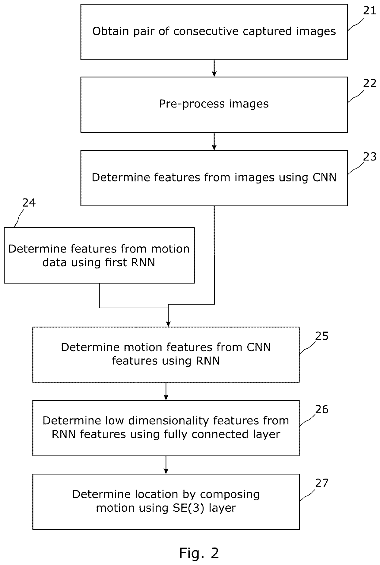
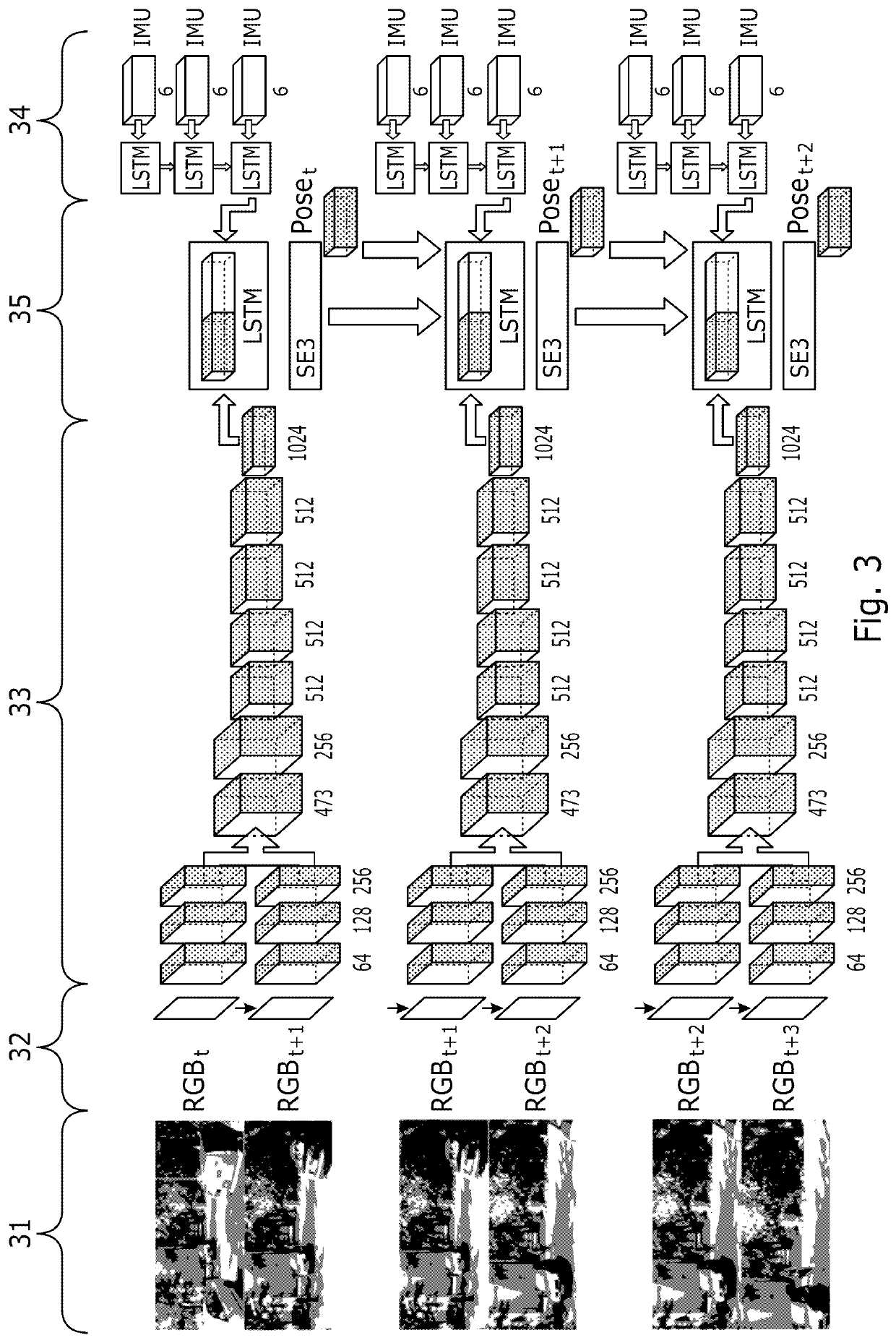
[0058]The operation of the autonomous robot 1 to determine its location is now described with reference to the flowchart of FIG. 2. The process is also shown schematically in FIG. 3. At each time step the autonomous robot 1 determines its location based on the information currently available to it. ...


PUM


Abstract

A computer-implemented method of determining the location of a mobile device comprising a camera and at least one inertial sensor. A sequence of images are captured over a period of time, and a first neural network determines features indicative of the motion of the device from pairs of consecutive images. Data indicative of the motion of the device is captured, and a second neural network determines features indicative of the motion of the device from the data. A third neural network then determines features indicative of the location of the device from the features determined by the first neural network and the second neural network. The location of the device is the determined from the features determined by the third neural network.

Description

FIELD OF THE INVENTION[0001]The present invention concerns determining the location of a mobile device. More particularly, but not exclusively, the invention concerns using neural networks to determine the location of a mobile device from a combination of images captured by a camera of the mobile device and motion information captured by inertial sensors of the mobile device.[0002]The invention is particularly, but not exclusively, applicable where the mobile device is an autonomous robot. However, the invention is also applicable to other types of mobile and wearable devices, such as mobile phones, smart watches and the like.[0003]“Location” as discussed herein may refer to absolute location, such as that a mobile device is at a position on the Earth defined by latitude and longitude, and may also refer to relative location with respect to another position (e.g. a mobile device is a distance and direction from an initial starting position). Determination of location also frequently...

Claims


Application Information

Patent Timeline
Patent Type & Authority Patents(United States)
IPC IPC(8): G06T7/73G06T7/246G06N3/08G05D1/02
CPCG06T7/73G05D1/027G05D1/0253G06N3/08G06T7/246G06T2207/10016G06T2207/20081G06T2207/20084G06T2207/30244G06T7/20G06T2207/30248G06T7/70G06N3/084G06N3/044G06N3/045
Inventor CLARK, RONALDWANG, SENTRIGONI, AGATHONIKI
Owner OXFORD UNIV INNOVATION LTD
Why Eureka
Try Eureka