Method of correcting color fringe and method of processing image data using the same

a color fringe and image data technology, applied in the field of data processing, can solve the problems of color fringe phenomenon that may become serious, color artifacts in near-saturation regions, and chromatic aberration is a type of color distortion, so as to maximize correlation and reduce calculation cost

Active Publication Date: 2020-01-14
SAMSUNG ELECTRONICS CO LTD +1
View PDF14 Cites 1 Cited by
  • Summary
  • Abstract
  • Description
  • Claims
  • Application Information

AI Technical Summary

Benefits of technology

[0006]Some exemplary embodiments provide a method of correcting a color fringe to reduce color distortion near an object boundary.
[0011]A method of correcting color fringes and a method of processing image data according to exemplary embodiments can correct color distortion such as color fringes without corrupting the original colors of the image by modeling the color difference CD with the logistic function LF while maximizing the correlation by using information of the undistorted region.
[0012]In addition, a method of correcting a color fringe and a method of processing image data according to exemplary embodiments can reduce a calculation cost by reducing the number of the parameters required to optimize the logistic function LF.

Problems solved by technology

When an image sensor captures a real scene color distortions such as a color fringe may occur near a boundary of an object in a digital color image.
The color fringe phenomenon may become serious when resolution of the digital color image increases and the image sensor is used for more detailed image acquisition.
Chromatic aberration is a type of color distortion that occurs when lenses of the image sensor do not focus light of different wavelengths on a convergence point.
When intense light is incident on the image sensor, the accumulated charge in a pixel may overflow into adjacent pixels and a blooming charge may cause color artifacts in a near-saturation region.

Method used


Image

  • Method of correcting color fringe and method of processing image data using the same
  • Method of correcting color fringe and method of processing image data using the same
  • Method of correcting color fringe and method of processing image data using the same

Examples


Embodiment Construction

[0030]Various exemplary embodiments will be described more fully hereinafter with reference to the accompanying drawings, in which some exemplary embodiments are shown. In the drawings, like numerals may refer to like elements throughout. The repeated descriptions may be omitted.

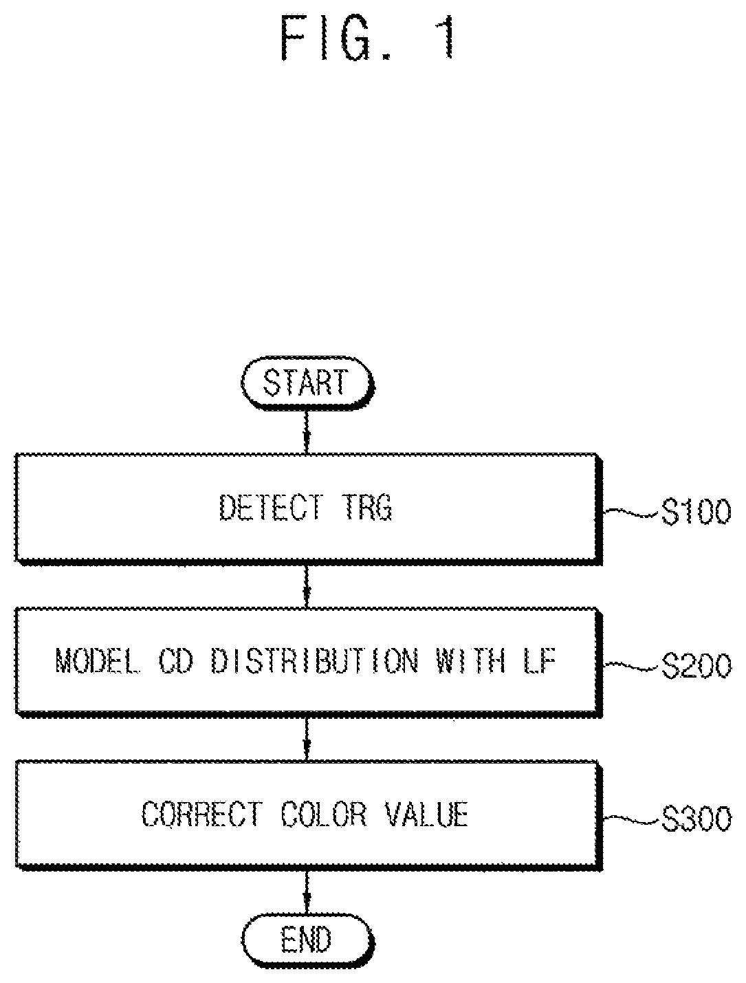
[0031]FIG. 1 is a flow chart of a method of correcting a color fringe according to exemplary embodiments.

[0032]Referring to FIG. 1, a transition region TRG is detected that includes pixels adjacent in a linear direction (S100). A distribution of color differences CD in the transition region TRG is modeled by a logistic function LF (S200). Color values of the pixels in the transition region TRG are corrected using the logistic function LF (S300). As will be described below, color values of the pixels in the transition region TRG can be corrected such that a correlation between a correction color and a reference color is maximized with respect to the transition region TRG. Color distortion, such as a color fri...


PUM


Abstract

A color fringe is corrected by detecting a transition region that includes pixels adjacent in a linear direction. A color difference distribution in the transition region is modeled by a logistic function. Pixel color values in the transition region are corrected using the logistic function to maximize a correlation between a correction color and a reference color with respect to the transition region. Color distortion such as color fringes is corrected without corrupting the original colors of the image by modeling the color difference by the logistic function while maximizing the correlation using information of the undistorted region. A calculation cost is reduced by reducing the number of the parameters required to optimize the logistic function.

Description

CROSS-REFERENCE TO RELATED APPLICATION[0001]This U.S. Non-provisional application claims priority under 35 USC § 119 from, and the benefit of, Korean Patent Application No. 10-2016-0018733, filed on Feb. 17, 2016 in the Korean Intellectual Property Office (KIPO), the contents of which are herein incorporated by reference in their entirety.BACKGROUND[0002]1. Technical Field[0003]Exemplary embodiments relate generally to data processing, and more particularly to a method of correcting a color fringe and method of processing image data.[0004]2. Discussion of the Related Art[0005]When an image sensor captures a real scene color distortions such as a color fringe may occur near a boundary of an object in a digital color image. The color fringe phenomenon may become serious when resolution of the digital color image increases and the image sensor is used for more detailed image acquisition. In general, the color fringe is caused by chromatic aberration in the optical system and the bloomi...

Claims


Application Information

Patent Timeline
Patent Type & Authority Patents(United States)
IPC IPC(8): G06T5/00G06T5/40H04N5/217H04N9/04
CPCG06T5/40G06T2207/10024G06T5/006H04N1/58H04N23/81H04N25/136H04N25/134
Inventor PARK, RAE-HONGJANG, DONG-WON
Owner SAMSUNG ELECTRONICS CO LTD
Why Eureka
Try Eureka