
Liquid Crystal Display Panel and Array Substrate Thereof

a liquid crystal display and array substrate technology, applied in the field of liquid crystal display techniques, can solve the problems of color drift, poor image clarity, and difficulty in adjusting the view angle, so as to improve the display result, reduce color distortion, and improve the effect of color difference in large view angle situation

Inactive Publication Date: 2013-12-19
SHENZHEN CHINA STAR OPTOELECTRONICS TECH CO LTD
View PDF6 Cites 9 Cited by
  • Summary
  • Abstract
  • Description
  • Claims
  • Application Information

AI Technical Summary

Benefits of technology

This patent describes a liquid crystal display panel and array substrate that can improve color difference and reduce color distortion in a 3D display mode. The panel achieves this by dividing the pixel electrode into three sub electrodes, with one designated as the default voltage difference when displaying the same image. This helps to solve the signal crosstalk problem and improve the color difference in large view angle situations, reducing color distortion and improving the overall display result. The panel also improves luminance and opening ratio in 2D display mode to further enhance the color difference and reduce color distortion.

Problems solved by technology

However, VA panel is deficient in screen uniformity so that color drift often occurs.
Also, FPR 3D displaying technique also suffers the problem of view angle restriction, i.e., the viewer has a narrower view angle.
This situation leads to serious image crosstalk and results in poor image clarity.
Therefore, when realizing FPR 3D displaying technique on VA display panel, the large view angle problem is severe.
After increasing width of BM 18, corresponding BM mask must also be modified and thus manufacture cost of liquid crystal display panel is increased.
In addition, VA display panel exists own color cast, the color anomaly observed by the viewer at position with large viewing angle is even more severe.

Method used


Image

  • Liquid Crystal Display Panel and Array Substrate Thereof
  • Liquid Crystal Display Panel and Array Substrate Thereof
  • Liquid Crystal Display Panel and Array Substrate Thereof

Examples


Embodiment Construction

[0046]The structure of an array substrate of liquid crystal display panel of the present invention improves the color difference in large view angle situation in both 2D and 3D display modes, reduces color distortion and improves display result.

[0047]The following description refers to drawings and embodiments of the present invention.

[0048]Referring to FIG. 3 and FIG. 4. An embodiment of array substrate 10 of liquid crystal display panel of the present invention comprises at least a plurality of first scan lines 101, second scan line 102, data lines 103 and a plurality of pixel units 104 arranged in a matrix form. In the instant embodiment, each of the pixel units 104 further comprises: switch element 1041 and pixel electrode 1042, and each of the pixel units 104 corresponds to at least a first scan line 101, a second scan line 102 and a data line 103.

[0049]Pixel electrode 1042 at least comprises a first sub electrode 10421, a second sub electrode 10422 and a third sub electrode 10...


PUM

PropertyMeasurementUnit
voltageaaaaaaaaaa
capacitanceaaaaaaaaaa
conductionaaaaaaaaaa

Abstract

The present invention provides a liquid crystal display panel and array substrate thereof. The array substrate includes at least a plurality of first scan lines, second scan lines, data lines and a plurality of pixel units arranged in a matrix form; pixel electrodes of pixel unit being divided into at least first sub electrode, second sub electrode and third sub electrode, and controlling first sub electrode and second sub electrode to have a default voltage difference when displaying voltage signal of a same image in 3D display mode. As such, the present invention can reduce signal crosstalk problem in 3D display mode, improve color difference in large view angle condition and reduce color distortion.

Description

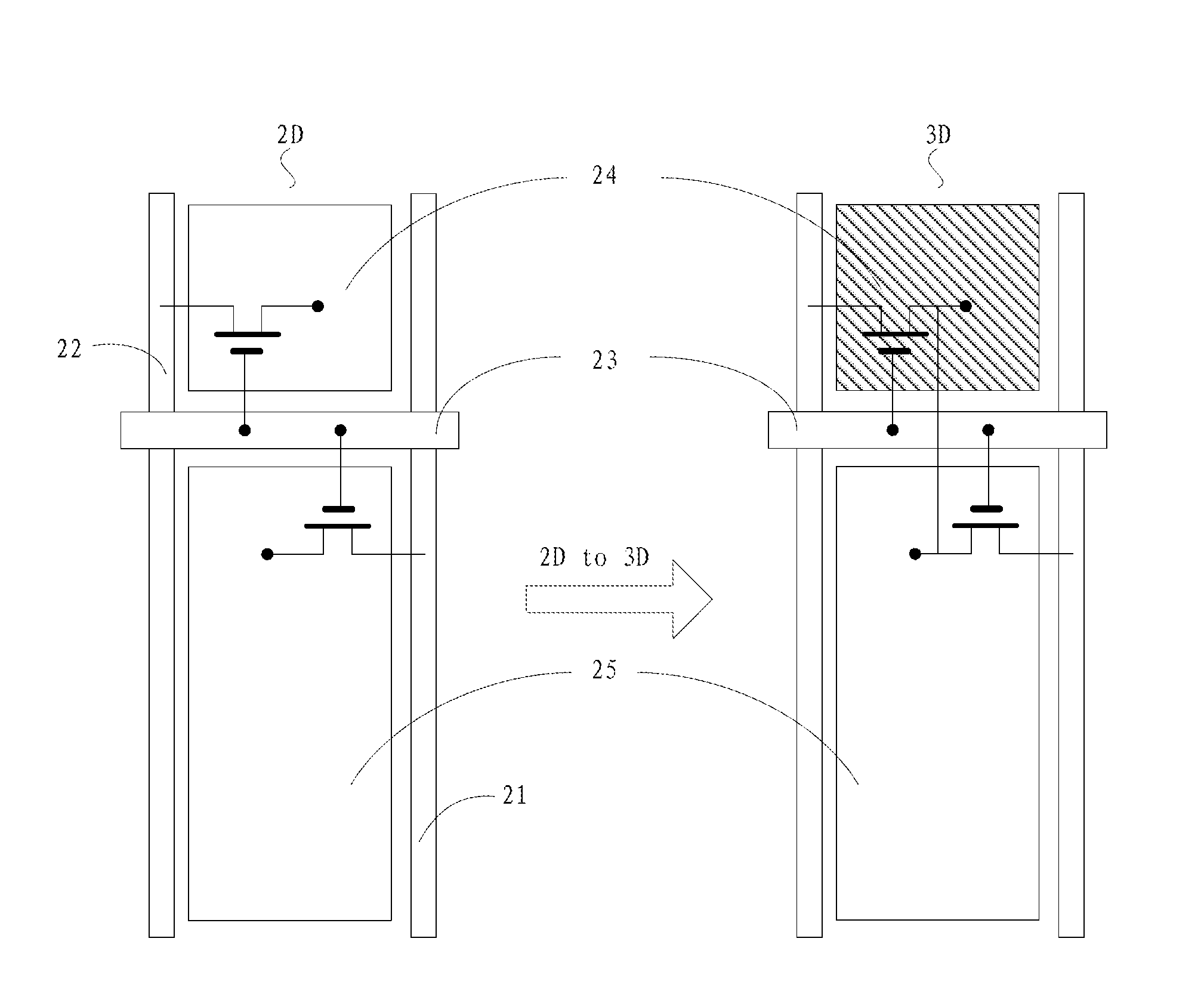
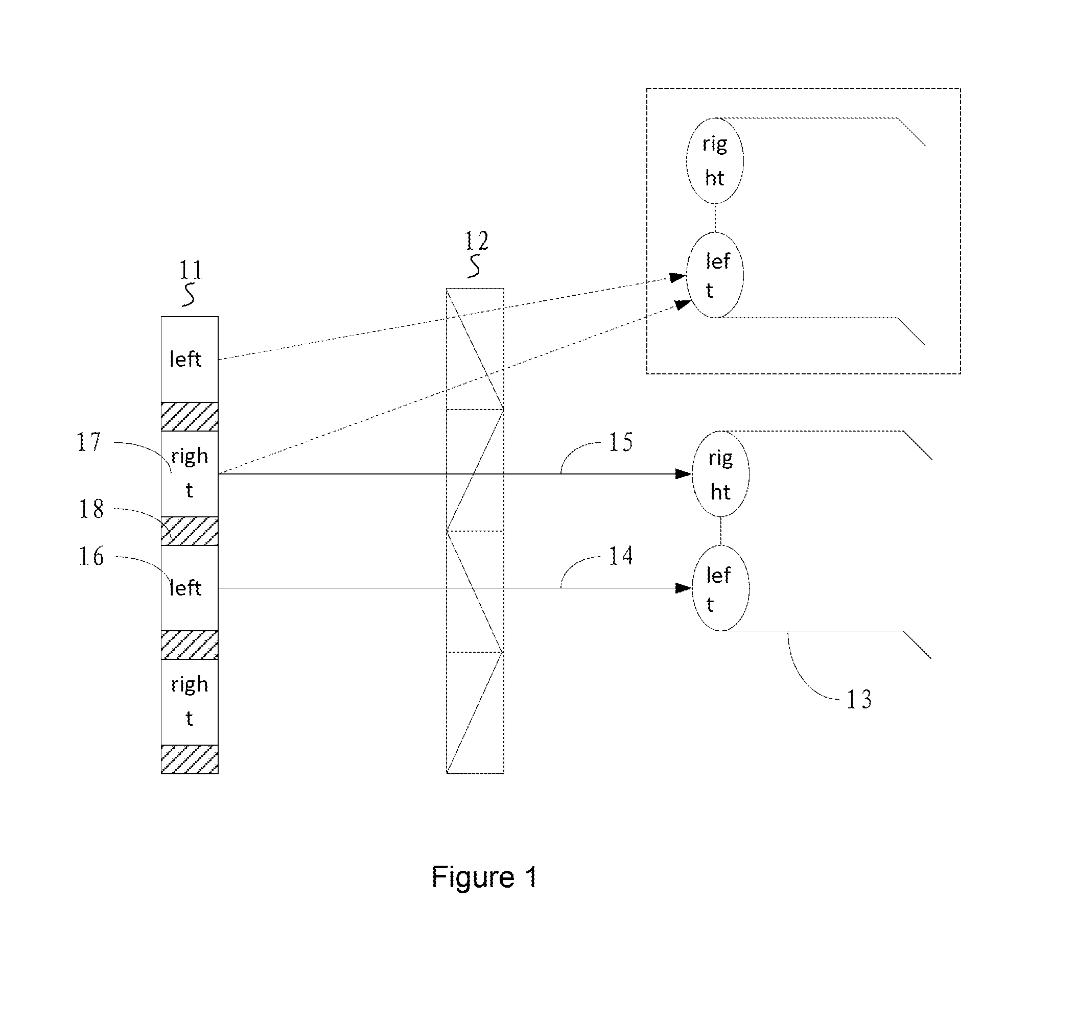
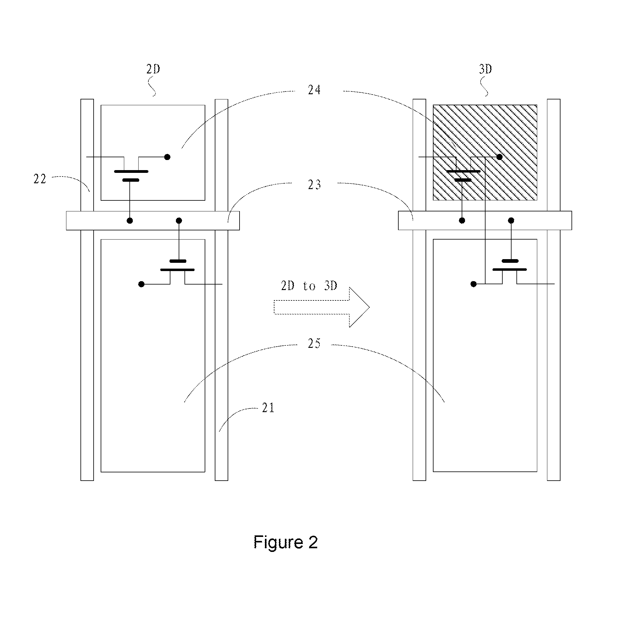
BACKGROUND OF THE INVENTION[0001]1. Field of the Invention[0002]The present invention relates to the field of liquid crystal displaying techniques, and in particular to a liquid crystal display panel and array substrate thereof.[0003]2. The Related Arts[0004]As the displaying technique continues to grow, the three dimensional (3D) displaying technique is also becoming more matured. A variety of 3D image equipments, such as, 3D TV, 3D projection, 3D camera, is becoming available in the market. Compared to a two dimensional (2D) displaying technique, the display of 3D displaying technique is more vivid and shows better visual effects. Three dimensional displaying is becoming a mainstream of the future display device.[0005]Film-type patterned retarder (FPR) is one of the 3D liquid crystal imaging techniques. As shown in FIG. 1, FPR 3D display system includes a liquid crystal display panel 11, patterned retarder thin film 12 and patterned retarder eyeglasses 13. Liquid crystal display p...

Claims


Application Information

Patent Timeline
Patent Type & Authority Applications(United States)
IPC IPC(8): G09G3/36
CPCG09G3/003G09G3/3648G09G2300/0447G09G2300/0842G09G2320/0242G09G2320/028H04N13/332H04N13/356H04N2213/001
Inventor WANG, ZUI
Owner SHENZHEN CHINA STAR OPTOELECTRONICS TECH CO LTD
Learn More