
Vape coil cleaning device

a cleaning device and vape coil technology, applied in the direction of cleaning process and apparatus, tobacco, chemistry apparatus and processes, etc., can solve the problems of users being forced to discard used coils, vape coils can become encrusted with residues from the vaporizing process, etc., to achieve convenient and thorough cleaning, and delay the need for replacemen

Active Publication Date: 2022-06-07
RIEHLMAN MARY BETH +3
View PDF3 Cites 0 Cited by
  • Summary
  • Abstract
  • Description
  • Claims
  • Application Information

AI Technical Summary

Benefits of technology

[0003]The present invention provides an approach for easily and thoroughly cleaning vape coils for reuse, thereby delaying the need to purchase replacement. In an embodiment, the present invention is a vape cleaning device having a base enclosing a fan oriented to direct air upwardly, a heat block suspended above the fan, a heating element coupled to the heat block, and a shield coupled to the base and having a central opening. A cup is removably positioned in the central opening of the shield to be in contact with the heat block. A vape coil holder is removably suspended from the cup so that a portion of the holder extends within the cup. The device also includes a set of control electronics for selectively energizing the heating element to warm the heat block to a predetermined temperature and to selectively energize the fan. The shield is structured to suspend the vape coil holder in the central opening when the cup is removed from the central opening. The set of control electronics are configured to operate the heating element for a predetermined heating time period for a cleaning cycle. The set of control electronics are also configured to operate the fan for a predetermined drying time period for a drying cycle.

Problems solved by technology

During use, however, the vape coil can become encrusted with residue from the vaporizing process.
As a result, users are forced to discard the used coil and purchase replacement coils on a regular basis.

Method used


Image

  • Vape coil cleaning device
  • Vape coil cleaning device
  • Vape coil cleaning device

Examples


Embodiment Construction

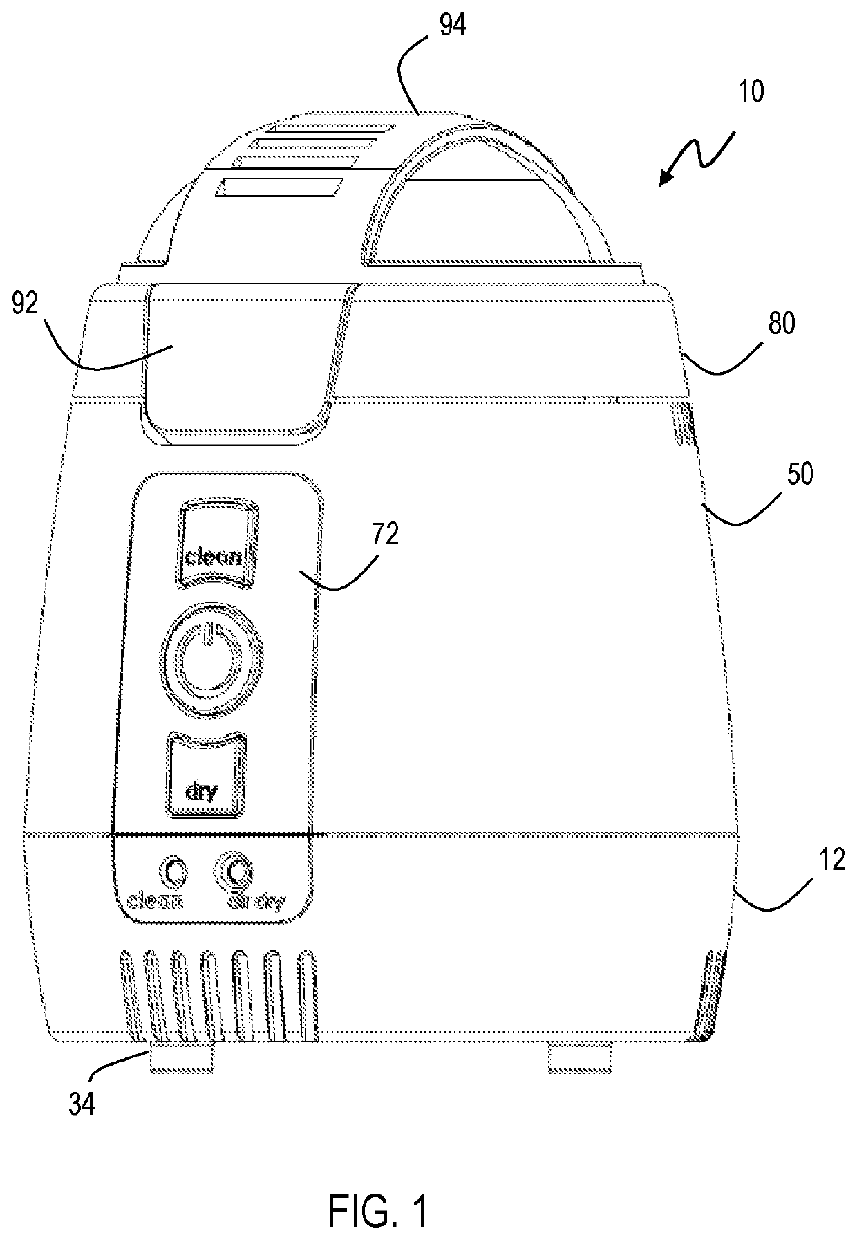
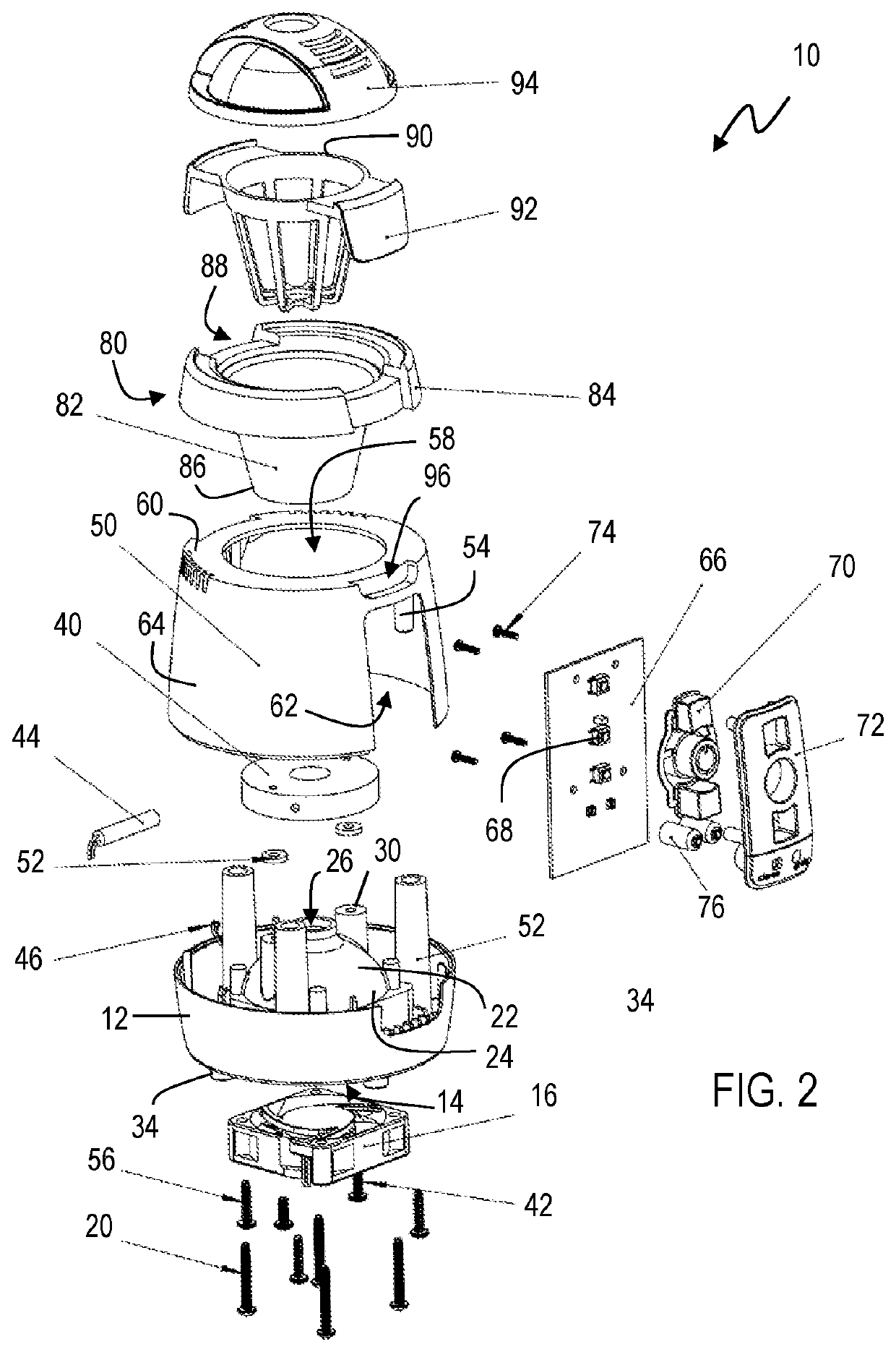
[0016]Referring to the figures, wherein like numeral refer to like parts throughout, there is seen in FIG. 1 a vape coil cleaning device 10. Device 10 comprises a base 12 having a cavity 14 thereunder that is dimensioned to receive a fan 16. Fan 16 may include a grill and is attached to base 12 within cavity 14 via a series of screws 20. Fan 16 moves air from the outside environment into device 10 when fan 16 is operated.

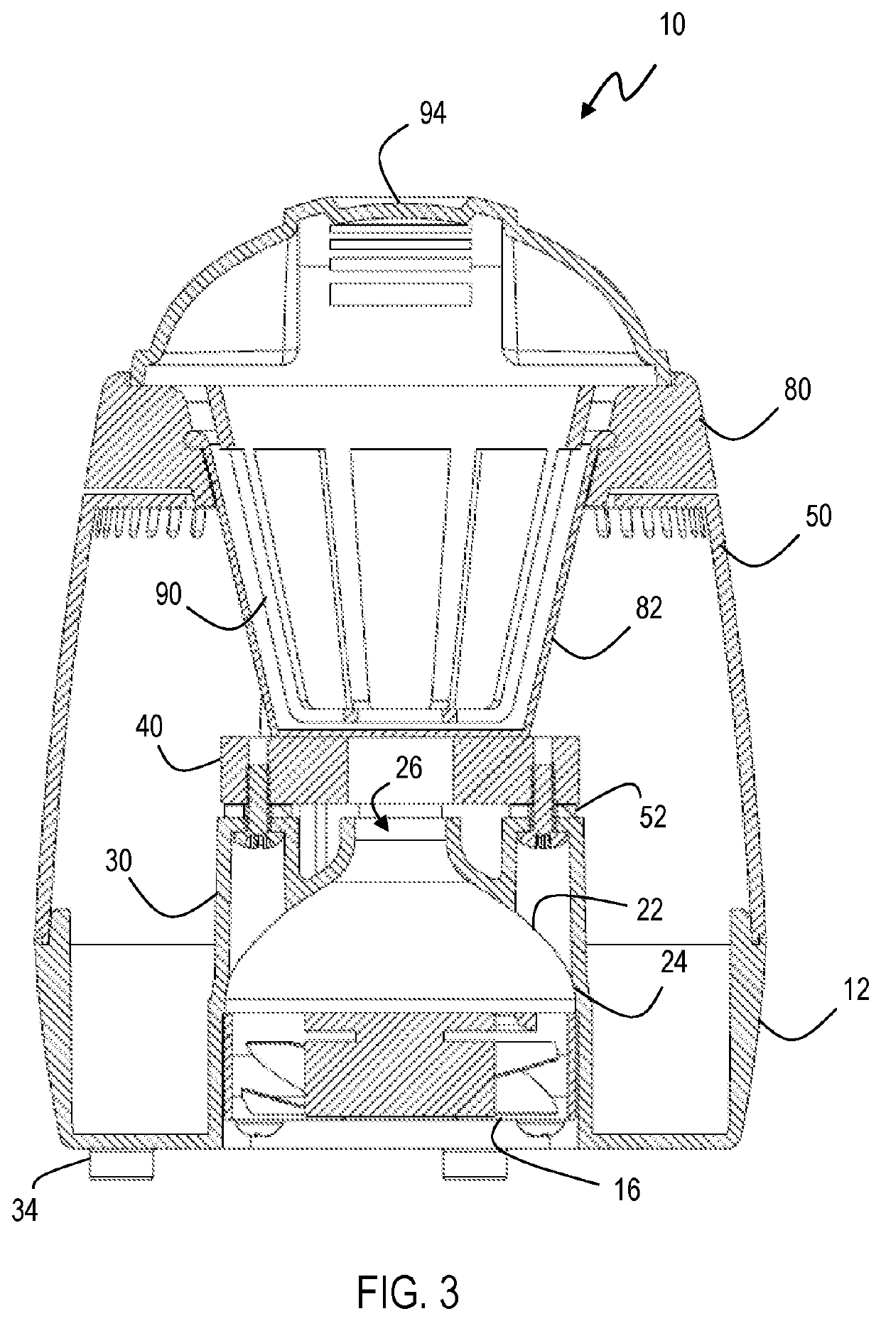
[0017]Base 12 includes a dome 22 having a lower mouth 24 with a diameter that encloses fan 16 and is in fluid communication with an upper outlet 26 having a reduced diameter so that air driven by fan 16 is directed through upper outlet 26. A set of bosses 30 extend upwardly from base 14. A heat block 40 is attached to bosses 30 using screws 42 so that heat block 40 is suspended above outlet 26 of dome 22. Washers 52 are interposed between heat block and bosses 30 to prevent overheating of bosses 30, Base 12 may include feet 34 for supporting device 10. A cartridge h...


PUM


Abstract

A vape cleaning device for easily and thoroughly cleaning vape coils for reuse and avoiding the need for frequent replacement. The device has a base enclosing a fan oriented to direct air upwardly, a heat block suspended above the fan, a heating element coupled to the heat block, and a shield coupled to the base and having a central opening. A cup is removably positioned in the central opening of the shield and in contact with the heat block to be heated thereby. A vape coil holder may removably suspended in the cup that the vape coil is submerged in a cleaning fluid in the cup. After the cup has been warmed to a predetermined temperature for a cleaning cycle, the cup may be removed and the vape coil holder suspended from the shield. The fan may then be operated for a predetermined time period for a drying cycle.

Description

BACKGROUND OF THE INVENTION1. Field of the Invention[0001]The present invention relates to vaping devices and, more specifically, to a cleaner for removing debris from the electrical coil of a vaping device.2. Description of the Related Art[0002]Vaping or vape devices, often referred to as electronic cigarettes, are handheld battery-powered vaporizers that simulate smoking without the need for tobacco combustion. Vaping devices include a mouthpiece, a cartridge (liquid storage area), a heating element / atomizer referred to as a vape coil, a microprocessor, and a power source such as a battery. The vape coil is used to vaporize the liquid in the cartridge for inhalation. During use, however, the vape coil can become encrusted with residue from the vaporizing process. As a result, users are forced to discard the used coil and purchase replacement coils on a regular basis. Accordingly, there is a need in the art for an approach that can be used to clean vape coils, thereby extending the...

Claims


Application Information

Patent Timeline
Patent Type & Authority Patents(United States)
IPC IPC(8): A24F40/85B08B7/00A24F40/44
CPCA24F40/85B08B7/0071A24F40/44B08B3/10
Inventor RIEHLMAN, MARY BETHBOCKLET, TERRY ANNELOGAN, MICHAEL J.MARCONI, JR., FRED A.
Owner RIEHLMAN MARY BETH
Learn More