
Medical implant for reducing pain in diseased joints

a technology for diseased joints and medical implants, applied in the field of medical implants for reducing pain in diseased joints, can solve the problems of inability to meet the needs of patients

Active Publication Date: 2018-05-15
BISPEBJERG HOSPITAL
View PDF13 Cites 0 Cited by
  • Summary
  • Abstract
  • Description
  • Claims
  • Application Information

AI Technical Summary

Benefits of technology

[0006]Therefore, the purpose of the present invention is to provide an implant which requires a lesser intervention to and around the diseased joint and natural bone structure, which limits the expenses in relation to e.g. hip surgery; preferably an implant that can at least delay the need for a full joint replacement, preferably for a minimum of 5 years.
[0008]The way the shell of the implant fits around the femoral head makes it possible that the implant is at least initially unconstrained when attached. Hence, the presently disclosed medical implant is preferably configured and / or arranged for at least initial unconstrained attachment to the natural femoral head. The implant can be press fit to a shaped femoral head and held in place by negative pressure and counter-pressure from acetabulum. Initially after insertion of the medical implant in a subject, the femoral head and the acetabulum can move against a smooth surface of the implant. The implant can thus be free to rotate relative to the femoral head as there is no risk that the implant is detached or misaligned due to the shape of the implant.
[0009]An unconstrained implant may be pushed to rotate relative to the joint parts by the natural motion of the hip thereby relieving friction even further. The implant may become attached to either the femoral head or the acetabulum by natural growth of different types of tissue over time, but the shell will remain able to provide pain relief to the joint as it will still be preventing (or at least reducing) friction between the femoral head and the acetabulum. If it becomes attached to the femoral head, the movement is between the acetabulum and the smooth outer surface of the medical implant, whereas if it becomes attached to the acetabulum the femoral head can move against the smooth inner surface of the medical implant. If the shell becomes attached it may in most cases be to the femoral head.
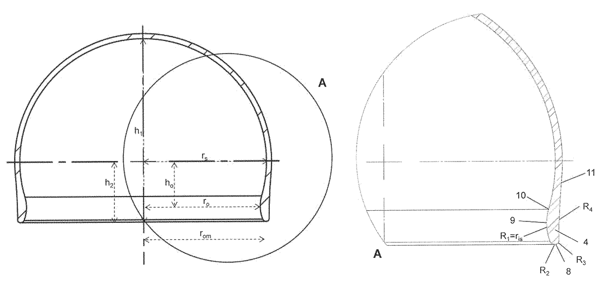
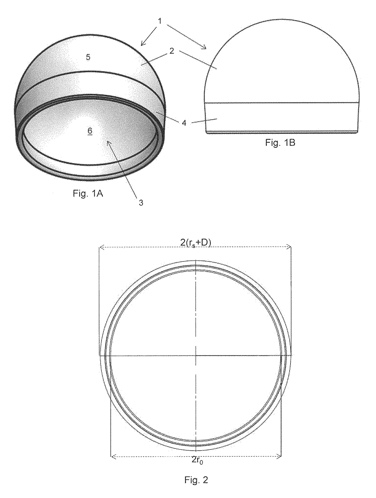
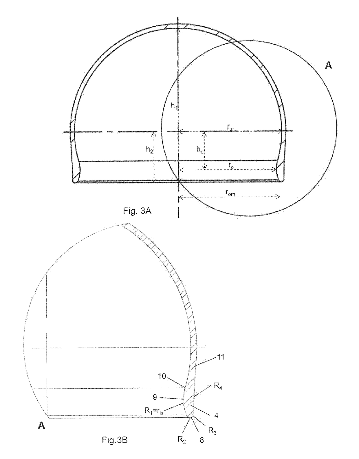
[0011]The dome is preferably a spherical dome, i.e. at least part of the shell may be spherical. The shell is furthermore preferably spherical to a position below the equatorial plane (aka the great circle of the shell. The medical implant preferably comprises a skirt zone below the equatorial plane of the shell. The properties of the skirt zone may be the same as the properties of the main shell. However, the implant may be configured such that the skirt zone has other properties, e.g. in terms of flexibility, thickness or curvature of the shell. The skirt zone may have properties selected to make attachment easier e.g. be flexible, have a specific surface, smooth etc. The skirt zone can also have properties which helps protect the femoral neck and surrounding tissue e.g. smooth surface and / or soft shape. The skirt zone can extend from the orifice towards the equator of the shell and can comprise at least the collar and the orifice. The inner surface of the shell and / or the outer surface of the shell of at least a part of said skirt zone may have a different curvature than the curvature of the shell above the equatorial plane. This change in curvature helps to the orifice such that the implant can be attached to the natural femoral head. Due to the shape of the femoral head and the shells dome shape where the equatorial radius of the shell is larger the radius of the orifice and where the height of the shell is larger than the equatorial radius of the shell, the shell can be pressed over the femoral head at a specified angle and thereby be attached as it encircles the dome of the femoral head and extends below the femoral head where the orifice encircles the femoral neck.
[0012]Thus, the presently disclosed medical implant is arranged to allow the shell to be attached around the femoral head from where it cannot be disengaged during normal hip alignment and movement as the diameter of the orifice of the shell is smaller than the largest diameter of the femoral head. When the implant is attached to the femoral head the orifice is below the femoral head i.e. it encircles part of the femur neck near the femoral head wherefore the rounded edge is an advantage as it prevents damage to the bone and tissue done by the edge of the orifice.

Problems solved by technology

However, complications may be caused by the replacement by artificial joints, in particular a high occurrence rate of loosening problems that may result in breakage of the bones around the artificial joint.
In particular, the invasive character of the fixation of the prostheses such as cementing or anchoring of the prosthesis with screws and pins result in side-effects such as risk of infection, loosening as mentioned above as well as luxation of the artificial hip joint, or periprosthetic fractures, damage on bone or interruption of blood supply possibly leading to necrosis.
However, the inherent designs of existing implants has not solved these problems, and problems persist with e.g. wear and creation of small particles released from one or more parts of the implants.
The known Smith-Petersen implants from the first half of the 20th century had problems with fixation and impingement due to the design of implants and the patient selection criteria.

Method used


Image

  • Medical implant for reducing pain in diseased joints
  • Medical implant for reducing pain in diseased joints
  • Medical implant for reducing pain in diseased joints

Examples


Embodiment Construction

[0042]As previously stated the dome is preferably a spherical dome or at least substantially a spherical dome as this shape fits around the natural femoral head and matches the spherical shape of the acetabulum. Further, a spherical curvature may provide a highly stable and stiff structure to at least the upper hemisphere of the shell. In other embodiments the shell can be other shapes, e.g. a more elliptical dome if this is preferred to obtain a better fit around a femoral head with a less rounded shape.

[0043]In one embodiment of the presently disclosed implant the inside surface of the shell is spherical to a first position below the equatorial plane. This first position may be seen as the intersection between a circle and the shell below the equatorial plane. The curvature of the inner surface preferably changes sign at this first position. The inner surface may thus curve in the opposite direction below said first position compared to the curvature of the inner surface above thi...


PUM


Abstract

The present invention relates to a medical implant for reducing pain in diseased joints such as synovial joints, in particular ball and socket joints such as the hip joint and the shoulder joint. One embodiment relates to a medical implant for attachment to and at least partly covering the femoral head, said medical implant comprising a dome shaped shell with an orifice, said shell having a height h1, an equatorial shell radius rs and an orifice radius ro wherein the shell radius rs>ro, and h1>rs, and the orifice is defined by a circumferential rounded edge.

Description

[0001]The present invention relates to a medical implant for reducing pain in diseased joints such as synovial joints, in particular ball and socket joints such as the hip joint and the shoulder joint.BACKGROUND OF INVENTION[0002]Joint damage, such as cartilage damage, is often treated by replacing the joint with an artificial joint. However, complications may be caused by the replacement by artificial joints, in particular a high occurrence rate of loosening problems that may result in breakage of the bones around the artificial joint.[0003]In particular, the invasive character of the fixation of the prostheses such as cementing or anchoring of the prosthesis with screws and pins result in side-effects such as risk of infection, loosening as mentioned above as well as luxation of the artificial hip joint, or periprosthetic fractures, damage on bone or interruption of blood supply possibly leading to necrosis.[0004]Manufacturers of prosthetic medical implants constantly work toward ...

Claims


Application Information

Patent Timeline
Patent Type & Authority Patents(United States)
IPC IPC(8): A61F2/36A61F2/30A61B17/16A61F2/34
CPCA61F2/3609A61B17/1668A61F2/30756A61F2/34A61F2/3603A61F2230/0093A61F2002/30703A61F2002/30705A61F2002/30757A61F2210/0076A61F2002/307
Inventor BRUUN LAURITZEN, JESLUND SPORRING, SUNE
Owner BISPEBJERG HOSPITAL
Learn More