Saccade detection and endpoint prediction for electronic contact lenses

a technology of electronic contact lenses and saccades, applied in the field of electronic contact lenses, can solve the problems of limited power budget for components within the contact lens, unique challenges of contact lenses, and limited placement of electrical components

Active Publication Date: 2022-06-07
TECTUS CORP
View PDF13 Cites 0 Cited by
  • Summary
  • Abstract
  • Description
  • Claims
  • Application Information

AI Technical Summary

Problems solved by technology

However, contact lenses present some unique challenges.
The placement of electrical components is further limited by the optical operation of the eye.
Furthermore, the power budget for components within the contact lens is limited.
Similarly, the available data bandwidth to the contact lens is also limited, presenting additional challenges.
As a result, it can be challenging to operate electrical components in an electronic contact lens.

Method used


Image

  • Saccade detection and endpoint prediction for electronic contact lenses
  • Saccade detection and endpoint prediction for electronic contact lenses
  • Saccade detection and endpoint prediction for electronic contact lenses

Examples


Embodiment Construction

[0017]The figures and the following description relate to preferred embodiments by way of illustration only. It should be noted that from the following discussion, alternative embodiments of the structures and methods disclosed herein will be readily recognized as viable alternatives that may be employed without departing from the principles of what is claimed.

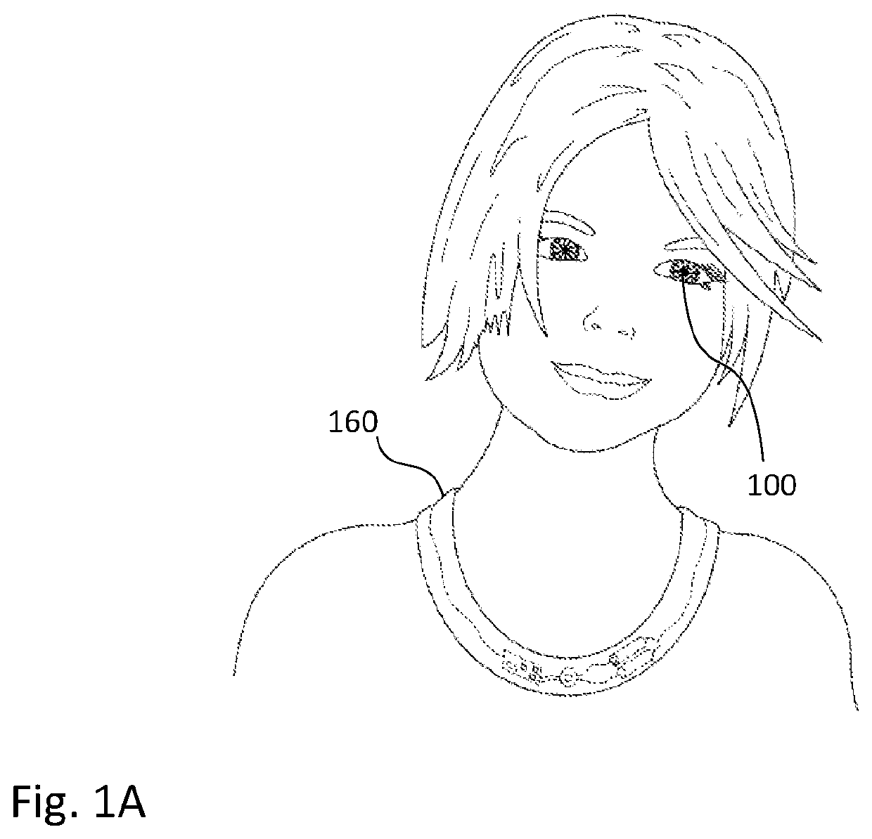
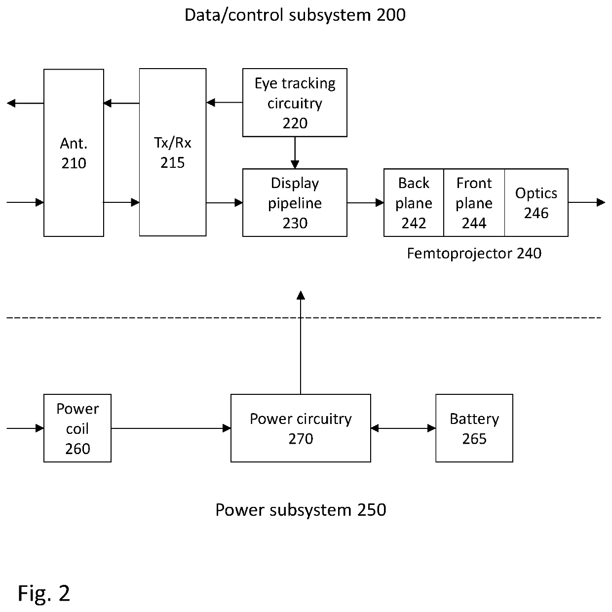
[0018]One type of electronic contact lens includes a display that is mounted on the user's eye. For example, such a device may include a scleral contact lens and one or more small projectors (femtoprojectors) contained in the contact lens. The femtoprojectors project images onto the user's retina. Because the display is eye-mounted, the femtoprojectors move with the eye, and the position of images displayed by the femtoprojectors relative to the external environment are affected by the eye movement. For example, if the femtoprojector projects an image to a constant location on the retina while the eye is moving, then the image...


PUM

PropertyMeasurementUnit
diameteraaaaaaaaaa
diameteraaaaaaaaaa
diameteraaaaaaaaaa

Abstract

Operation of an electronic contact lens takes into account saccadic motion of the eye and reduced visual perception during saccades (saccadic suppression). The user's eye motion is tracked, and onset of a saccade is detected based on the eye's motion. For example, saccades may be detected when the eye's acceleration or jerk exceeds a threshold. The endpoint of the saccade is then predicted in real-time while the saccade is still occurring. This may be the temporal endpoint (i.e., when the saccade ends) and / or the positional endpoint (i.e., the eye position at the end of the saccade). Operation of the electronic contact lens is adjusted based on the predicted endpoint.

Description

BACKGROUND1. Technical Field[0001]This disclosure relates generally to electronic contact lenses, for example contact lenses containing projectors that project images onto the user's retina.2. Description of Related Art[0002]Contact lenses that provide refractive vision correction are commonplace. Recently, there has been increased interest in contact lenses that perform functions other than just vision correction. In many of these applications, a contact lens may carry a payload for performing various functions. For example, a contact lens may contain a payload of one or more electrical components, such as projectors, imaging devices (imagers), sensors, coils, batteries, MEMS (micro-electro-mechanical systems), accelerometers and magnetometers, etc. These contact lenses may be referred to as electronic contact lenses.[0003]However, contact lenses present some unique challenges. For example, they have a limited thickness and volume and they are inherently curved rather than planar. ...

Claims


Application Information

Patent Timeline
Patent Type & Authority Patents(United States)
IPC IPC(8): G02C7/04G02B27/00G02B1/04G02C7/08G02B27/01
CPCG02C7/049G02B1/043G02B27/0093G02C7/047G02C7/083G02B27/0101G02C7/048G02C7/04G02C7/086G02B27/0172G02B2027/0178
Inventor BHAT, ABHISHEK DEEPAKCZOMPO, JOSEPHMIRJALILI, RAMINWIEMER, MICHAEL WESTANDERSON, ERIK
Owner TECTUS CORP
Why Eureka
Try Eureka