Eye position control monitor for laser vision correction

a laser vision correction and monitor technology, applied in laser surgery, medical science, diagnostics, etc., can solve the problems of high cost, high complexity, and imperfect optical system of human eye, and achieve the effect of reducing the number of eye surgeries, and improving the accuracy of eye surgery

Inactive Publication Date: 2005-11-22
TECHNOLAS PERFECT VISION
View PDF27 Cites 5 Cited by
  • Summary
  • Abstract
  • Description
  • Claims
  • Application Information

AI Technical Summary

Benefits of technology

[0010]The present invention is directed to a system for stabilizing a selected base point on an optical axis of a patient's eye. As contemplated by the present invention, the system includes an optical element for identifying the base point on the optical axis of the patient's eye. In addition, the optical element may be used to monitor changes in the relative position and stability of the base point, to determine a resting period in a heartbeat sequence of the patient, and a relaxation period in the patient's respiration cycle. The system also includes an illumination source which can be moved from a first position or orientation to a second position. In accordance with the present invention, the illumination source can be a light source which serves as a fixation point for the eye. Importantly, when the light source is moved between the first position and the second position, a saccadic movement of the eye ensues. Following the saccadic movement of the eye, there is a latency period during which the base point, and hence the eye, is substantially stabilized.
[0014]When the light source is moved from the first position to the second position, a saccadic movement of the eye occurs. This saccadic movement realigns the optical axis of the eye with the light source. When the light source is subsequently moved back to the first position, a second saccadic eye movement takes place. During the latency period that follows the second saccadic eye movement, the base point is substantially stabilized. If the location of the base point is within an acceptable margin of error (i.e. ±20 μm), and the optical axis is properly aligned with the system as verified by the alignment device, photoablation may proceed. Stated differently, in the preferred embodiment of the present invention, photoablation of the corneal tissue occurs after the base point is stabilized in the first position, and the alignment of the optical axis is properly verified.
[0015]It can be appreciated by those skilled in the art that it is possible to photoablate corneal tissue with each saccadic movement of the eye. Thus, in an alternate embodiment of the present invention, photoablation occurs while the eye is stabilized, and the optical axis is aligned, in both the first and the second positions. To accurately determine both the first and the second positions of the eye, a wavefront sensor consisting of a wavefront analyzer and an active mirror can be used. The wavefront sensor can also be used to help define a new surgical pattern, as necessary, after each saccadic eye movement. As each new surgical pattern is defined, photoablation may proceed.

Problems solved by technology

The human eye is a very delicate, complex, and imperfect optical system.
Over much of the last 250 years, techniques for measuring and correcting the optical impairments of the eye have been limited to addressing nearsightedness or farsightedness, and the corresponding cylindrical refractive errors.
The human eye, however, also shows higher order refractive errors, or so-called “higher aberrations”.
As a result, light rays pass through the peripheral regions in the eye where greater refractive errors are present.
Simple refractive errors, like nearsightedness or farsightedness, normally result in a simple bowl-like, symmetrical wavefront distortion.
Higher order aberrations, however, can yield a more complex, non-symmetrical distortion of the originally flat wavefront, which is unique for every person's eye.
These wavefront distortions will then lead to blurred optical imaging of viewed scenes.
When eyeglasses are inadequate to make the necessary improvements, refractive surgery may be necessary.
It happens, however, that stabilization of the eye through only saccadic eye movement may not be adequate, in many instances, to allow for laser cutting.

Method used


Image

  • Eye position control monitor for laser vision correction
  • Eye position control monitor for laser vision correction

Examples


Embodiment Construction

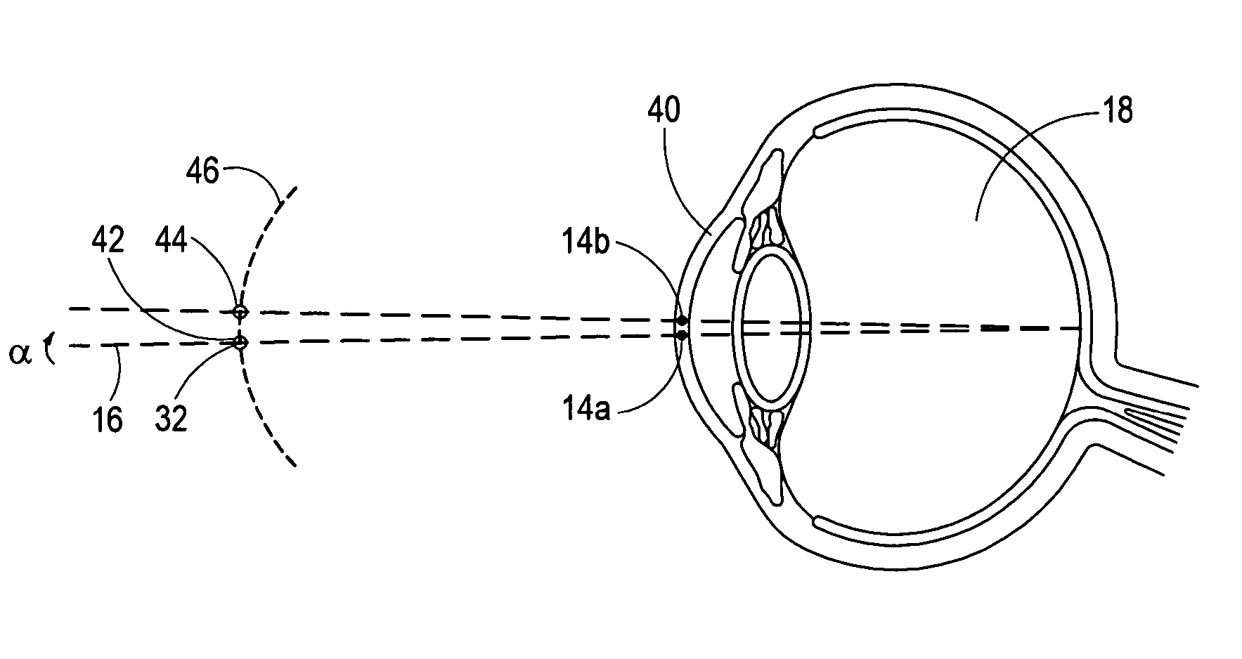
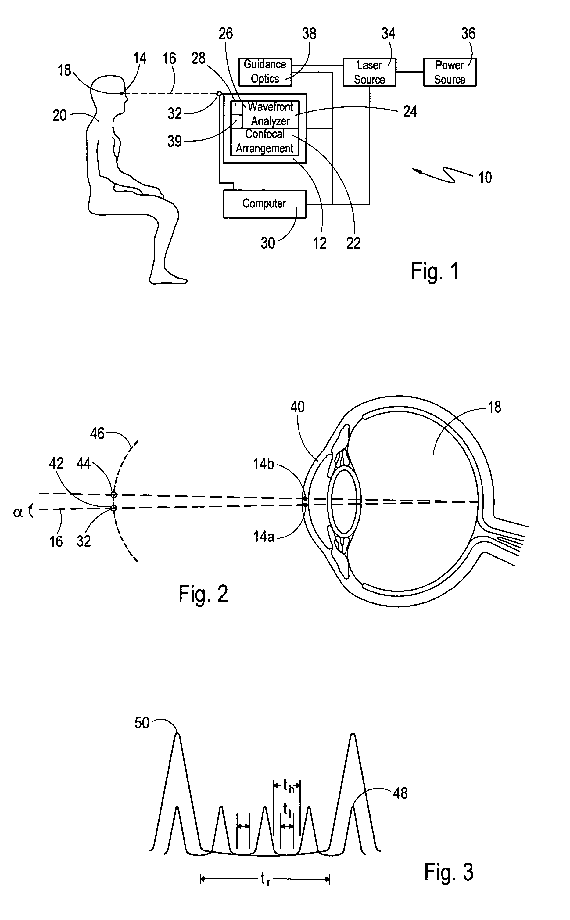
[0020]A system in accordance with the present invention is shown in FIG. 1 and generally designated 10. As shown in FIG. 1, the system 10 includes an optical element 12 for identifying a base point 14 on an optical axis 16 of the eye 18 of a patient 20. More specifically, the optical element 12 comprises a confocal arrangement 22 and a wavefront sensor 24. The wavefront sensor 24 further comprises a wavefront analyzer 26 and an active mirror 28. In one embodiment of the present invention, the confocal arrangement 22 is used to identify the base point 14 of the eye 18. In an alternate embodiment, the wavefront sensor 24, consisting of the wavefront analyzer 26 and active mirror 28, is used to identify the base point 14. The use of the confocal arrangement 22 or the wavefront sensor 24 is dictated by the operational mode of the system 10, as further described below. As shown in FIG. 1, the optical element 12 is in electronic communication with a computer controller 30.

[0021]As contemp...


PUM


Abstract

A system for spatially stabilizing a base point on the optical axis of a patient's eye, for photoablation of the cornea, includes an optical element for identifying the base point. The system also includes an illumination source which is a fixation point for the eye. Movement of the illumination source induces a saccadic movement of the eye wherein the optical axis of the eye moves from a first orientation to a second orientation. Following the saccadic movement of the eye there is a latency period during which the base point, and hence the eye, is substantially stabilized. Movement of the light source is timed to coincide the latency period with the resting period of the patient's heartbeat sequence, and the relaxation period of the patient's respiration cycle. During the latency period, photoablation is accomplished by directing a train of laser pulses from a laser source into the corneal tissue.

Description

FIELD OF THE INVENTION[0001]The present invention pertains generally to systems and methods for ophthalmic laser surgery. More particularly the present invention pertains to the photoablation of corneal tissue by a continuous train of laser pulses during time periods when the eye is in a relatively stable position. The present invention is particularly, but not exclusively, useful as a system for spatially stabilizing a selected base point on the optical axis of a patient's eye for photoablation of the corneal tissue by inducing a saccadic movement of the eye at a predetermined moment in time.BACKGROUND OF THE INVENTION[0002]The human eye is a very delicate, complex, and imperfect optical system. Over much of the last 250 years, techniques for measuring and correcting the optical impairments of the eye have been limited to addressing nearsightedness or farsightedness, and the corresponding cylindrical refractive errors. The human eye, however, also shows higher order refractive erro...

Claims


Application Information

Patent Timeline
Patent Type & Authority Patents(United States)
IPC IPC(8): A61B3/113A61F9/01A61F9/007
CPCA61B3/0091A61B3/1015A61B3/113A61F9/00806A61F2009/00846A61F2009/00872A61F2009/0088
Inventor BILLE, JOSEF
Owner TECHNOLAS PERFECT VISION
Why Eureka
Try Eureka