Moving body control apparatus
a control apparatus and body technology, applied in vehicle maintenance, vehicle cleaning, television systems, etc., can solve the problem of more frequent fogging of the window part which falls within the camera field of view
- Summary
- Abstract
- Description
- Claims
- Application Information
AI Technical Summary
Benefits of technology
Problems solved by technology
Method used
Image
Examples
first embodiment
[0019]
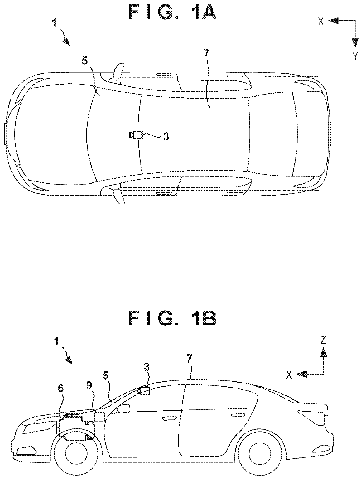
[0020]A vehicle control apparatus 20 according to the first embodiment will be described below. FIGS. 1A and 1B are a plan view and a side view, respectively, of a vehicle 1 according to an embodiment. Note that in each drawing, an arrow X indicates the front-and-rear direction of the vehicle 1, and an arrow Y indicates the vehicle width direction of the vehicle 1. An arrow Z indicates the vertical direction.
[0021]The vehicle 1 is, for example, a sedan-type four-wheeled vehicle. The vehicle 1 includes two seats in the front row adjacent to a window part 5, and two seats in the rear row. The right seat in the front row is the driver's seat, and the left seat is the passenger seat. The vehicle 1 includes a total of four doors adjacent to the seats. A driving unit 6 is provided in the front part of the vehicle 1. The driving unit 6 includes a driving source that generates the driving force of the vehicle 1. In this embodiment, the driving source is an engine (internal combustion ...
second embodiment
[0045]The operation of a heater 4 is started when the ambient temperature is equal to or less than a predetermined temperature in the first embodiment. However, the second embodiment differs from the first embodiment in the point that the operation of the heater is started when a change amount ΔT3 of an ambient temperature T3 per predetermined time is equal to or more than a predetermined threshold. Note that in this embodiment, the change amount ΔT3 is positive when the ambient temperature has decreased after a predetermined time has elapsed. That is, the change amount ΔT3 is the amount of reduction of the ambient temperature T3 per predetermined time, and the operation of the heater is started when this amount of reduction is equal to or more than a predetermined value.
[0046]For example, in a case in which the vehicle enters a tunnel or a sudden rainfall occurs while a driving operation is being performed, a window part 5 may become fogged due to the sudden temperature change even...
third embodiment
[0053]Although different conditions for starting the operation of a heater 4 are set between the inside air circulation state and the outside air introduction state in the first and second embodiments, it is also possible to adopt an arrangement in which the operation condition, which is set while the heater 4 is in operation, differs between the inside air circulation state and the outside air introduction state. In the third embodiment, the output at the time of the heater operation is made higher in the inside air circulation state than that in the outside air introduction state so that fogging of a window part 5 (a transmitting portion 50) can be removed or prevented more effectively when the in-vehicle air-conditioning state is set to the inside air circulation state in which the fogging of the window part 5 (the transmitting portion 50) is more likely to occur.
[0054]FIG. 7 is a flowchart showing an example of processing executed by an ECU 24 when the heater 4 is in operation a...
PUM
 Abstract
Description
Claims
Application Information
 - R&D
- Intellectual Property
- Life Sciences
- Materials
- Tech Scout
- Unparalleled Data Quality
- Higher Quality Content
- 60% Fewer Hallucinations
Browse by: Latest US Patents, China's latest patents, Technical Efficacy Thesaurus, Application Domain, Technology Topic, Popular Technical Reports.
© 2025 PatSnap. All rights reserved.Legal|Privacy policy|Modern Slavery Act Transparency Statement|Sitemap|About US| Contact US: help@patsnap.com


