Systems and methods for adjusting light output

a technology of light output and system, applied in the direction of electrical devices, etc., can solve the problems of affecting the usefulness of light sensors in relation to practical applications, complicating the absolute reading of ambient light sensors, and reducing aesthetic uniformity, so as to reduce or eliminate the effect of light feedback

Active Publication Date: 2022-08-09
NANOGRID LTD (HK)
View PDF7 Cites 0 Cited by
  • Summary
  • Abstract
  • Description
  • Claims
  • Application Information

AI Technical Summary

Benefits of technology

[0006]To maximize aesthetic uniformity between modules, the light sensor is placed behind optical elements within the panel, hidden from direct view by an observer (e.g., for aesthetic purposes such that the modular lighting appears to the observers as a fully lit object). This introduces light feedback from the lighting elements (e.g., LEDs) in the panel that must be factored out to obtain accurate readings that reflect true ambient light levels in a room coming from other light sources. Having the light sensor obstructed yields technical challenges from a sensory perspective and a specific approach for calibration is described in various embodiments that allows for a practical implementation of lighting devices where the sensor is placed behind the optical elements within the panel.
[0008]As described in various embodiments, compensation mechanisms are provided that aid in reducing or eliminating effects of light feedback.

Problems solved by technology

Modulating output brightness levels of a system based on ambient light input is a technically challenging endeavor, as multiple considerations must be accounted for.
In particular, maintaining aesthetic uniformity is challenging, especially in view of light feedback (e.g., from reflections, internal structures).
Further, if the internal lighting elements (e.g., LEDs) are in transition, either in terms of output brightness or in terms of output colour, this can further complicate absolute readings from an ambient light sensor.
Accordingly, there are technical challenges in respect of obtaining accurate readings from the light sensor, and these challenges can impede the usefulness of the light sensor in relation to practical applications, such as generating accurate control signals for the adjustment of light output.

Method used


Image

  • Systems and methods for adjusting light output
  • Systems and methods for adjusting light output
  • Systems and methods for adjusting light output

Examples


Embodiment Construction

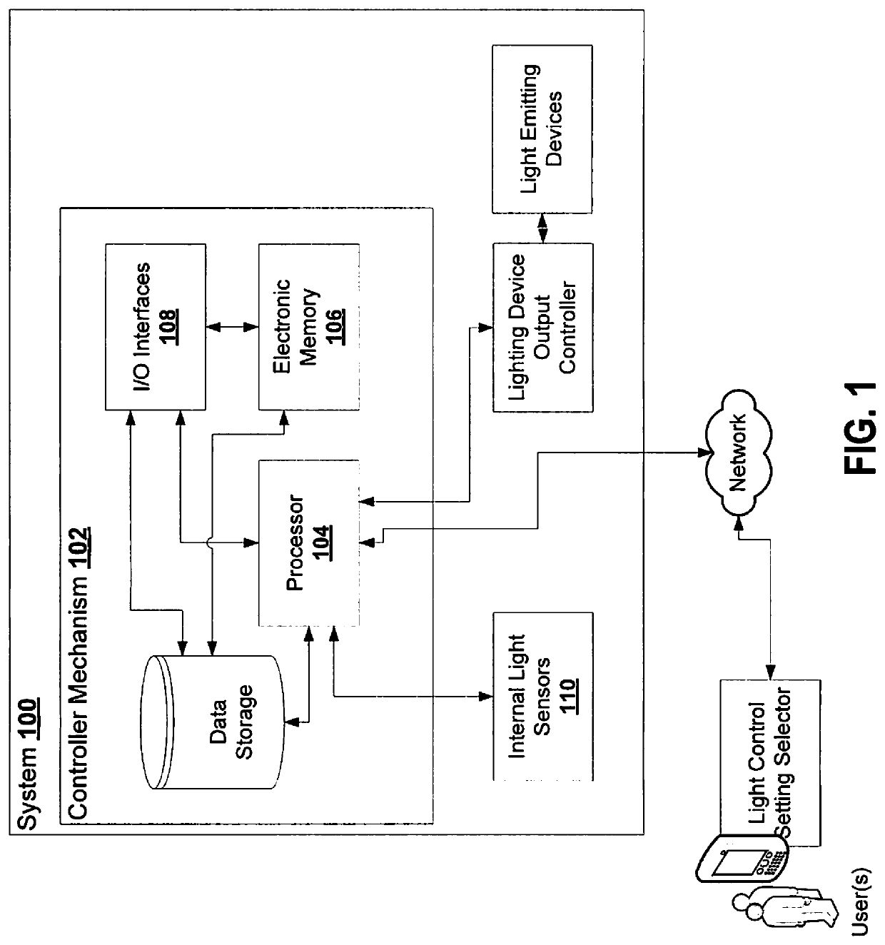
[0025]As described in various embodiments, compensation mechanisms are provided that aid in reducing or eliminating effects of light feedback.

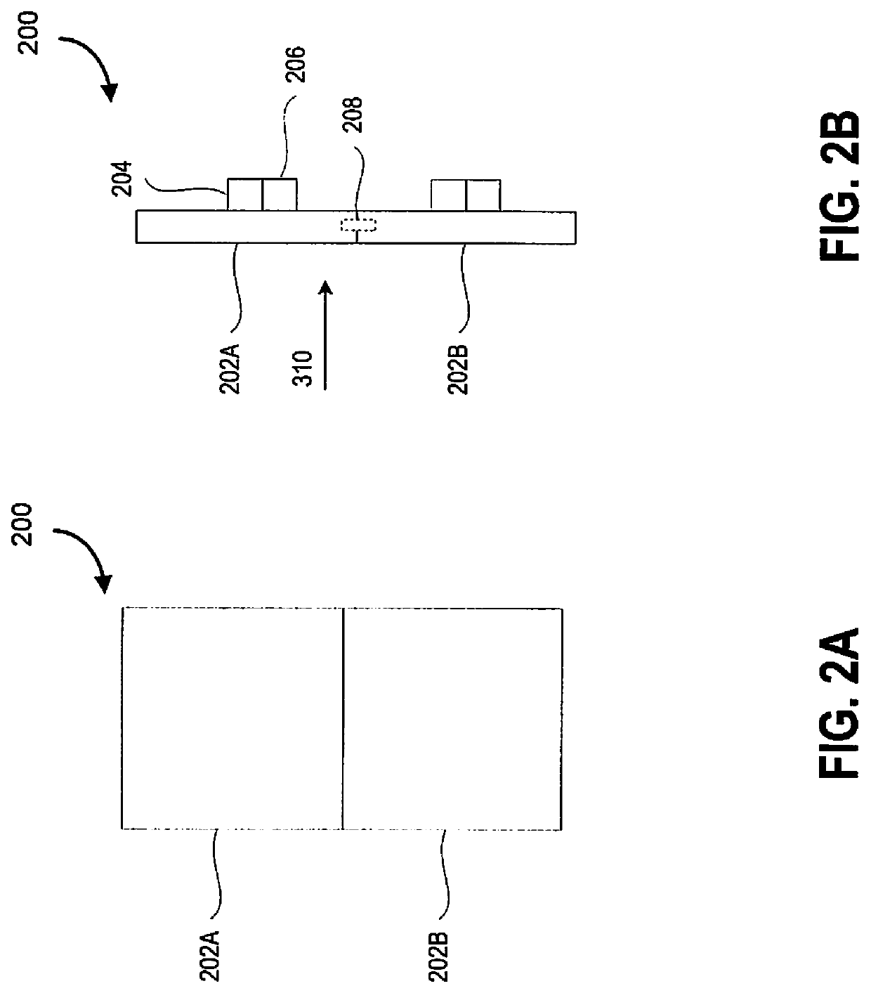
[0026]Modulating output brightness levels of a system based on ambient light input is a technically challenging endeavor, as multiple considerations must be accounted for. To maximize aesthetic uniformity between modules, in some embodiments, the light sensor is placed behind optical elements within the panel, hidden from direct view by an observer (e.g., for aesthetic purposes such that the modular lighting appears to the observers as a fully lit object).

[0027]This introduces light feedback from the lighting elements (e.g., LEDs) in the panel that must be factored out to obtain accurate readings that reflect true ambient light levels in a room coming from other light sources.

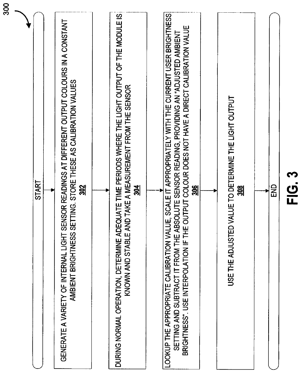
[0028]Having the light sensor obstructed yields technical challenges from a sensory perspective and a specific approach for calibration is described in various embodiment...


PUM


Abstract

Embodiments of the present disclosure generally relate to the field of controlling light output, and more specifically, embodiments relate to devices, systems and methods for modulating output brightness levels of a system based on ambient light input. In particular, systems and methods for compensating for light feedback are described, along with systems and methods for determining output lighting states based on relative light levels, and methods for calibration of self-feedback values.

Description

CROSS-REFERENCE[0001]This application is a non-provisional of, and claims all benefit including priority to, U.S. Application No. 62 / 803,976, entitled “SYSTEMS AND METHODS FOR ADJUSTING LIGHT OUTPUT”, filed Feb. 11, 2019, incorporated herein by reference.FIELD[0002]Embodiments of the present disclosure generally relate to the field of controlling light output, and more specifically, embodiments relate to devices, systems and methods for modulating output brightness levels of a system based on ambient light input.INTRODUCTION[0003]Modulating output brightness levels of a system based on ambient light input is a technically challenging endeavor, as multiple considerations must be accounted for. In particular, maintaining aesthetic uniformity is challenging, especially in view of light feedback (e.g., from reflections, internal structures).SUMMARY[0004]Controllable lighting is desirable, and lighting devices having adjustable light output adapted for control in accordance with modulati...

Claims


Application Information

Patent Timeline
Patent Type & Authority Patents(United States)
IPC IPC(8): H05B47/11H05B47/175H05B45/20H05B45/10
CPCH05B47/11H05B45/10H05B45/20H05B47/175H05B45/12
Inventor ESKI, ALIAKBAR JUZERDYCK, NATHANZHANG, LEI
Owner NANOGRID LTD (HK)
Why Eureka
Try Eureka