Clamping device

a technology of clamping device and clamping state, which is applied in the field of clamping device, can solve the problems of not being able to accommodate variations in the thickness of the workpiece, the clamping device may not be able to lock the clamp arm, and the lock of the clamping state may be released, so as to achieve sufficient clamping state, stable clamping force, and increase the stability of the clamping state.

Active Publication Date: 2022-08-16
SMC CORP
View PDF16 Cites 0 Cited by
  • Summary
  • Abstract
  • Description
  • Claims
  • Application Information

AI Technical Summary

Benefits of technology

[0005]The present invention has been devised taking into consideration the aforementioned problems, and has the object of providing a clamping device capable of establishing an excellent locking state and, at the same time, capable of satisfactorily accommodating variations in the thickness of a workpiece by increasing a lock range.
[0007]Since the clamping device described above includes the push mechanism elastically pushing the displacement body, the displacement body can be displaced without being interfered, and the guide surface of the displacement body can be brought into firm contact with the clamp arm or the rotation portion while the clamp arm is in the clamping state. Thus, the reliability of the lock (rotation control) of the clamp arm increases, resulting in a sufficient clamping state even when, for example, the size of the clamping device is small. In addition, even when the clamp arm is in the clamping state, the elastic push of the push mechanism provides a lock range allowing variations in the thickness of the workpiece by displacing the displacement body a certain distance. Thus, the clamping device allows dimensional errors in the workpiece and the clamping device and demonstrates stable clamping force.

Problems solved by technology

This may cause release of the lock of the clamping state in the clamping device in a case where the clamp reaction force is large.
Moreover, in a case where the thickness of the workpiece varies due to dimensional errors and the like, the piston rod may not reach a predetermined advanced position (position where the clamp arm is locked) even when the clamp arm clamps the workpiece, and the clamping device may not be able to lock the clamp arm.
That is, the known clamping device has a narrow lock range to lock the clamping state of the clamp arm, and cannot accommodate variations in the thickness of the workpiece.

Method used


Image

  • Clamping device
  • Clamping device
  • Clamping device

Examples


Embodiment Construction

[0015]A preferred embodiment according to the present invention will now be described with reference to the accompanying drawings.

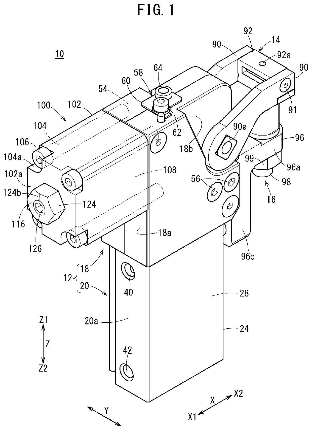
[0016]As illustrated in FIG. 1, a clamping device 10 according to an embodiment of the present invention includes a body 12, a clamp arm 14 rotated relative to the body 12, and a support structure 16 secured to the body 12. The clamp arm 14 holds a workpiece W (see FIG. 4) between the clamp arm 14 and the support structure 16 to create a clamping state (gripping state). For example, a plurality of clamping devices 10 are attached to an end effector of a mobile robot in an automotive production line and cooperate with each other to hold and move a shaped part (workpiece W) such as a panel.

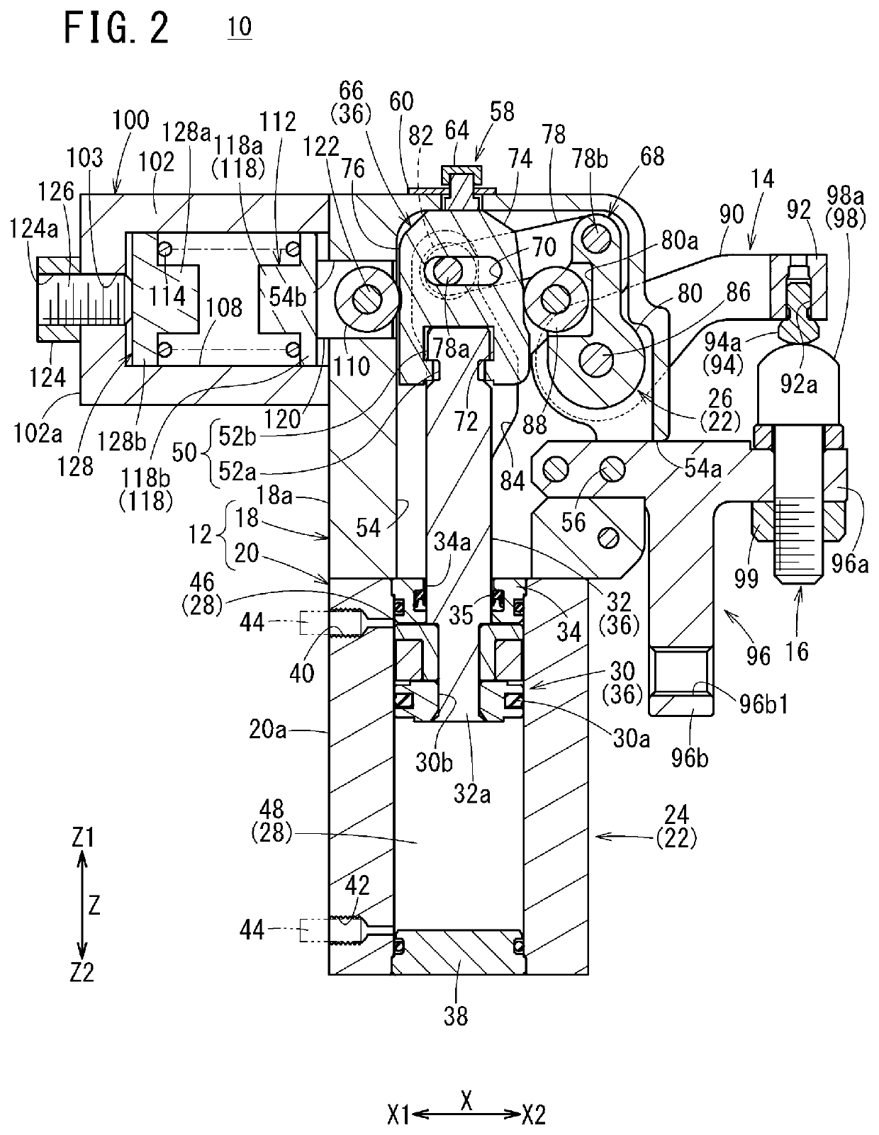
[0017]The body 12 includes a first housing 18 to which the clamp arm 14 is provided to be rotatable and a second housing 20 connected with a lower end part (on a side at which an arrow Z2 is pointing; hereinafter referred to as “Z2 side”) of the first housing 18. As illus...


PUM


Abstract

A clamping device includes a body, a clamp arm and a drive mechanism that includes a displacement body displaced linearly, wherein the clamp arm is rotated based on the displacement of the displacement body. The displacement body includes a guide surface for guiding the rotation of the clamp arm, and also for controlling the rotation of the clamp arm while the clamp arm is in a clamping state. The clamping device further includes a push mechanism disposed at a position facing a lever arm and elastically pushing the displacement body toward the lever arm.

Description

TECHNICAL FIELD[0001]The present invention relates to clamping devices configured to clamp workpieces.BACKGROUND ART[0002]Japanese Laid-Open Patent Publication No. 2010-179429 discloses a clamping device clamping a workpiece using a clamp arm by rotating the clamp arm based on displacement of a piston and a piston rod. The clamping device includes link mechanisms (first link and second link) disposed between the piston rod and the clamp arm, and the piston rod is provided with, on a side surface adjacent to an end thereof, an inclined part (wedge surface) coming into contact with a curved portion of the clamp. That is, the clamping device uses the link mechanisms to convert the displacement of the piston rod into the rotational motion of the clamp arm, and uses the wedge surface to guide the rotation of the clamp arm and control (lock) the rotation of the clamp arm when the workpiece is in a clamped state.SUMMARY OF INVENTION[0003]As described in Japanese Laid-Open Patent Publicatio...

Claims


Application Information

Patent Timeline
Patent Type & Authority Patents(United States)
IPC IPC(8): B25B5/06B25B5/12B25B5/16
CPCB25B5/064B25B5/122B25B5/16
Inventor SEO, TAKESHI
Owner SMC CORP
Why Eureka
Try Eureka