
Electrostatic energy storage welding machine

a technology of energy storage welding machine and electrostatic energy storage, which is applied in the direction of welding monitoring device, electrode feature, manufacturing tools, etc., can solve the problems of difficulty in high cost, and difficulty in achieving speeding up the process, so as to speed up the process, time to eliminate the variation, and the effect of increasing the cos

Pending Publication Date: 2022-02-24
NAG SYST
View PDF0 Cites 0 Cited by
  • Summary
  • Abstract
  • Description
  • Claims
  • Application Information

AI Technical Summary

Benefits of technology

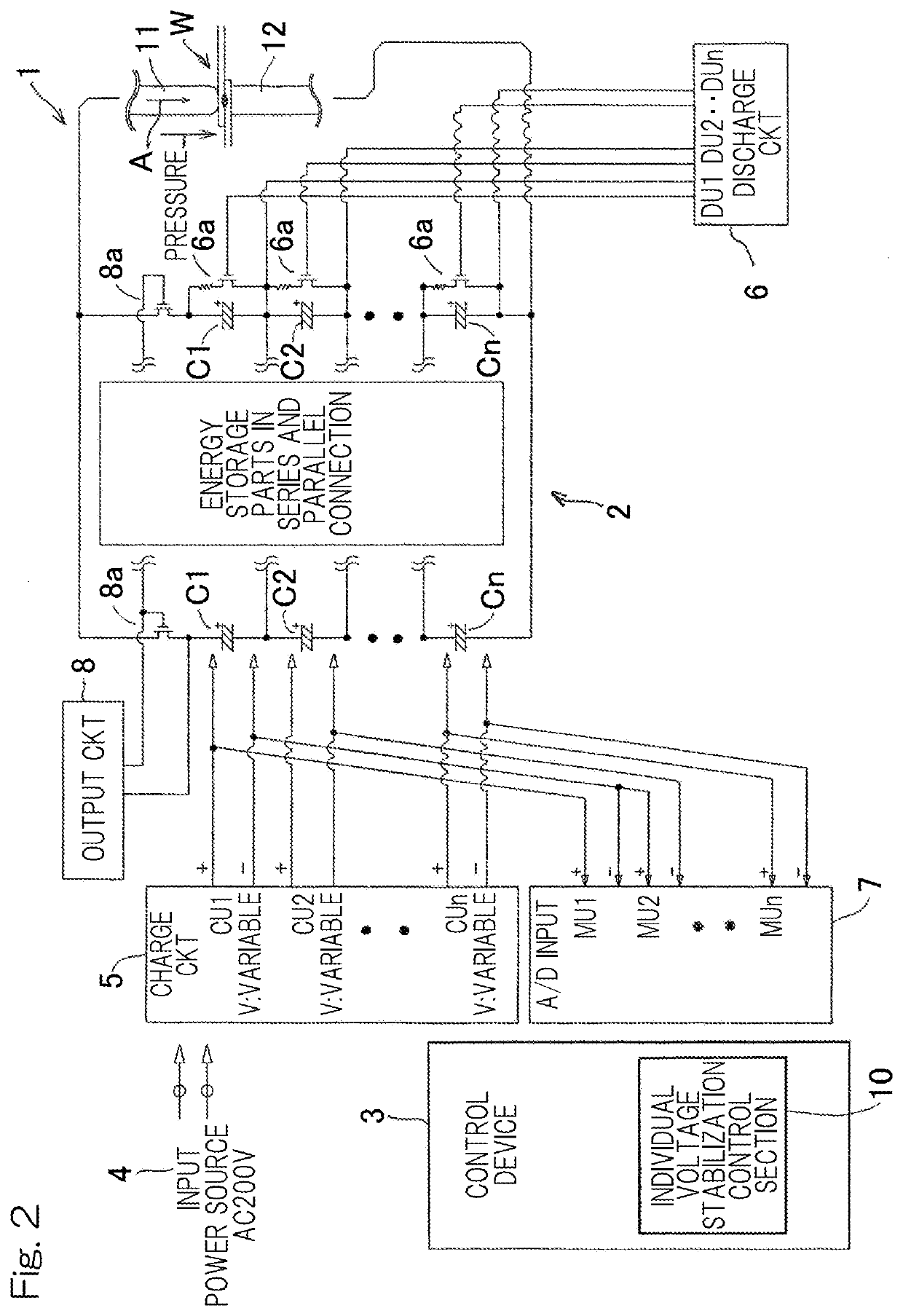
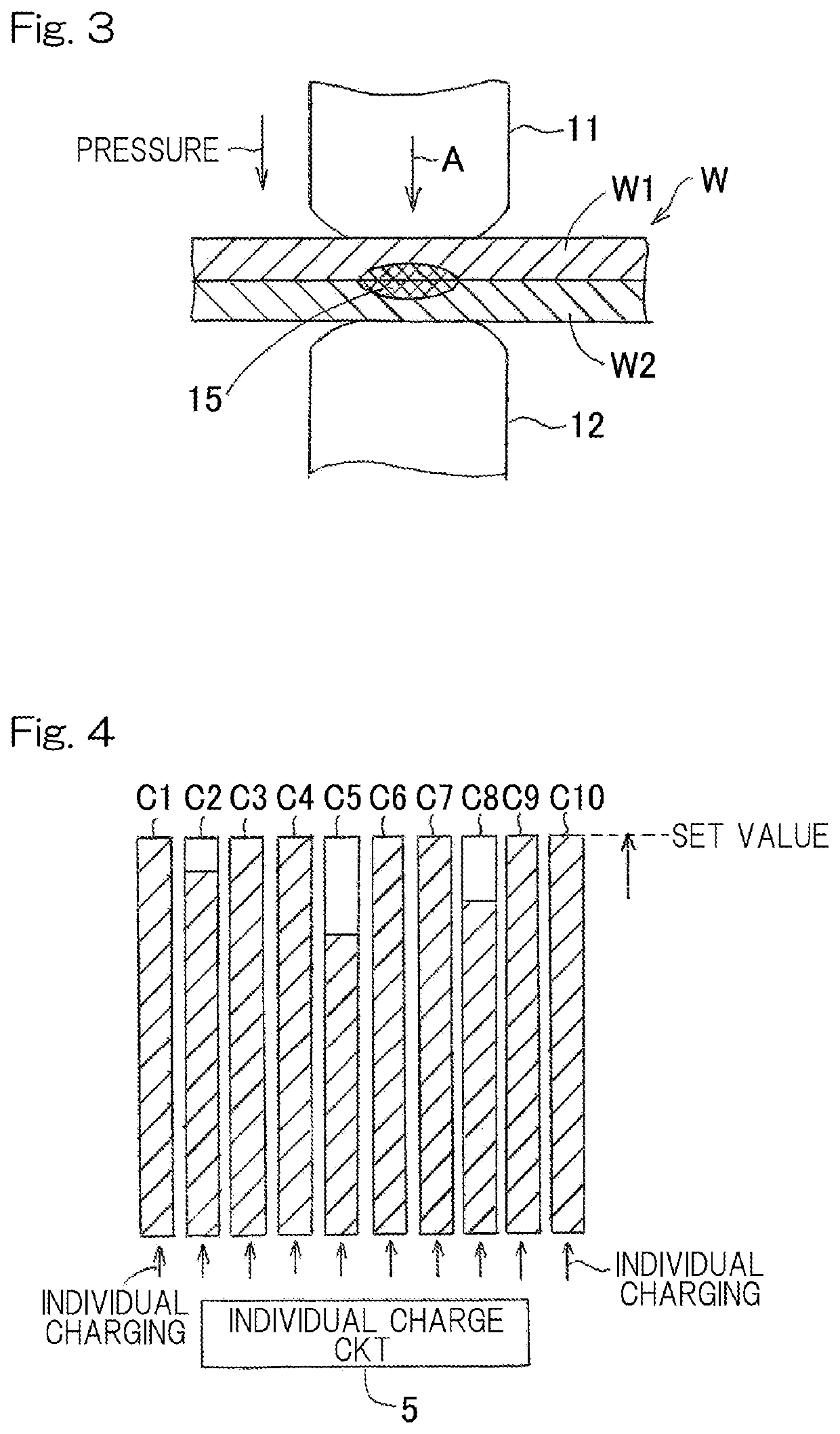
The present invention provides an electrostatic energy storage welding machine capable of accommodating variation in performance among a plurality of energy storage parts and efficiently outputting large power with a set voltage and a large electric current during welding so as to speed up resistance welding. By individually monitoring and charging / discharging each energy storage part in a divided manner, the machine can match the voltage to the set voltage more accurately, improve efficiency, and shorten the charging and discharging time. Insufficiently charged energy storage parts can be concentratedly charged to eliminate variations and stabilize voltage. Furthermore, the machine's individual discharge circuit prevents inflow of an electric current between energy storage parts and helps retain a large electric current while shortening the time required for discharging. As a result, the machine can speed up resistance welding and improve production efficiency.

Problems solved by technology

Therefore, it takes time to eliminate the variation, making it difficult to achieve speeding up of the process.
In addition, since this method includes pausing of a capacitor bank, it is necessary to provide an extra capacitor bank for substitution, which results in higher costs.
This method, however, merely detects overdischarging of a capacitor(s) having a deviation by discharging the entire system does not perform individual discharging, so that it is difficult to speed up the process.

Method used


Image

  • Electrostatic energy storage welding machine
  • Electrostatic energy storage welding machine
  • Electrostatic energy storage welding machine

Examples


Embodiment Construction

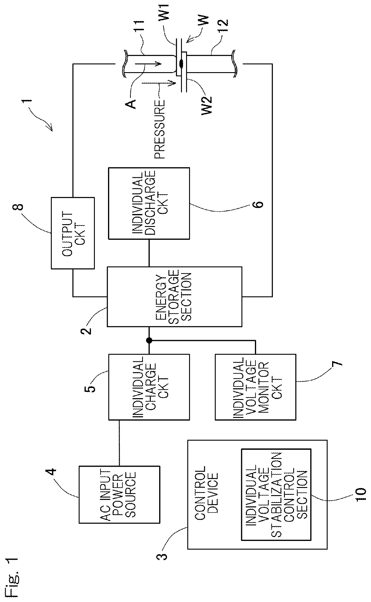
[0028]Hereinafter, an embodiment of the present invention will be described with reference to the drawings. FIG. 1 is a schematic diagram showing an electrostatic energy storage welding machine (hereinafter, simply referred to as “welding machine”) 1 according to an embodiment of the present invention. The welding machine 1 includes an energy storage section 2 including a plurality of large-capacity energy storage parts C and is configured to perform resistance welding of an object W to be welded by supplying large power while applying pressure to the object W to be welded between welding electrodes. This welding machine is suitable in a case where there is variation in performance among the respective energy storage parts C and in a case of resistance welding which requires, e.g., conduction of a large electric current for a short period of time and speeding up of the production processes.

[0029]The welding machine 1 includes a pair of upper and lower welding electrodes 11, 12 which...


PUM

PropertyMeasurementUnit
voltagesaaaaaaaaaa
pressureaaaaaaaaaa
voltagesaaaaaaaaaa

Abstract

An electrostatic energy storage welding machine for performing resistance welding while applying pressure to an object to be welded includes: a pair of welding electrodes; an energy storage section including a plurality of energy storage parts; an individual charge circuit for individually charging respective energy storage parts; an individual discharge circuit for individually discharging the respective energy storage parts; a voltage monitor circuit individually monitoring voltages of the respective energy storage parts; an individual voltage stabilization control section for performing control to further charge an energy storage part having deviation in performance in an individual manner to stabilize a voltage of that energy storage part and thereby achieve a set voltage; and an output circuit for outputting power produced by the set voltage stabilized through individual charging and electric current through individual discharging in the energy storage section to apply the electric current between the welding electrodes.

Description

CROSS REFERENCE TO THE RELATED APPLICATION[0001]This application is based on and claims Convention priority to Japanese patent application No. 2020-138934, filed Aug. 19, 2020, the entire disclosure of which is herein incorporated by reference as a part of this application.BACKGROUND OF THE INVENTIONField of the Invention[0002]The present invention relates to an electrostatic energy storage welding machine.Description of Related Art[0003]A conventionally known electrostatic energy storage welding machine includes an energy storage section including a plurality of large-capacity energy storage parts and is configured to perform resistance welding of an object to be welded by supplying large power while applying pressure to the object to be welded between welding electrodes. Such an electrostatic energy storage welding machine uses multiple energy storage parts such as large-capacity capacitors, which may have variation in performance. This type of electrostatic energy storage welding...

Claims


Application Information

Patent Timeline
Patent Type & Authority Applications(United States)
IPC IPC(8): B23K11/30B23K11/36B23K11/25B23K11/24
CPCB23K11/3009B23K11/241B23K11/258B23K11/364H02J7/0068H02J2207/50B23K11/26B23K11/18B23K11/185B23K11/115B23K11/252H02J7/02H02J7/0063B23K11/11H01M10/441
Inventor NAGAMINE, HIDEMASAWADA, KEIJI
Owner NAG SYST
Learn More