
Razor head

a razor head and head technology, applied in the field of shaving, can solve the problems of disordered hair roots, increased number of shaving, poor shaving effect, etc., and achieve the effects of less shaving resistance, increased comfort of shaving, and reduced shaving number

Active Publication Date: 2022-09-06
WENZHOU MERS R&D LTD
View PDF22 Cites 0 Cited by
  • Summary
  • Abstract
  • Description
  • Claims
  • Application Information

AI Technical Summary

Benefits of technology

The present invention provides a razor head with improved shaving comfort and efficiency. The front side wall of the razor head has multiple protective ribs that guide the hair roots and reduce shaving resistance. The protective ribs and guide grooves help the hair to align and be shaved with less resistance. This results in a smooth shaving experience and reduces the number of shavings required. Additionally, the front protective rib increases the comfort of the razor head when it comes into contact with the skin, while the rear protective rib reduces skin deformation and ensures that the hair in the guide groove aligns properly. Overall, this razor head design provides better shaving performance and comfort.

Problems solved by technology

Because the existing razor head flattens the hair roots by the convex strips of the skin contact member, and their shaves the hair roots, the hair roots are disorderly during the flattening process.
On the one hand, shaving effect is poor, and the number of shaving is increased; on the other hand, the flattened hair roots cannot be ensured to be perpendicular to a cutting direction of the blades, so there is a defect of large shaving resistance, thereby resulting in poor shaving comfort.

Method used


Image

  • Razor head
  • Razor head
  • Razor head

Examples


Embodiment Construction

[0025]A distinct and full description of the technical solution of the present invention will follow by combining with the accompanying drawings.

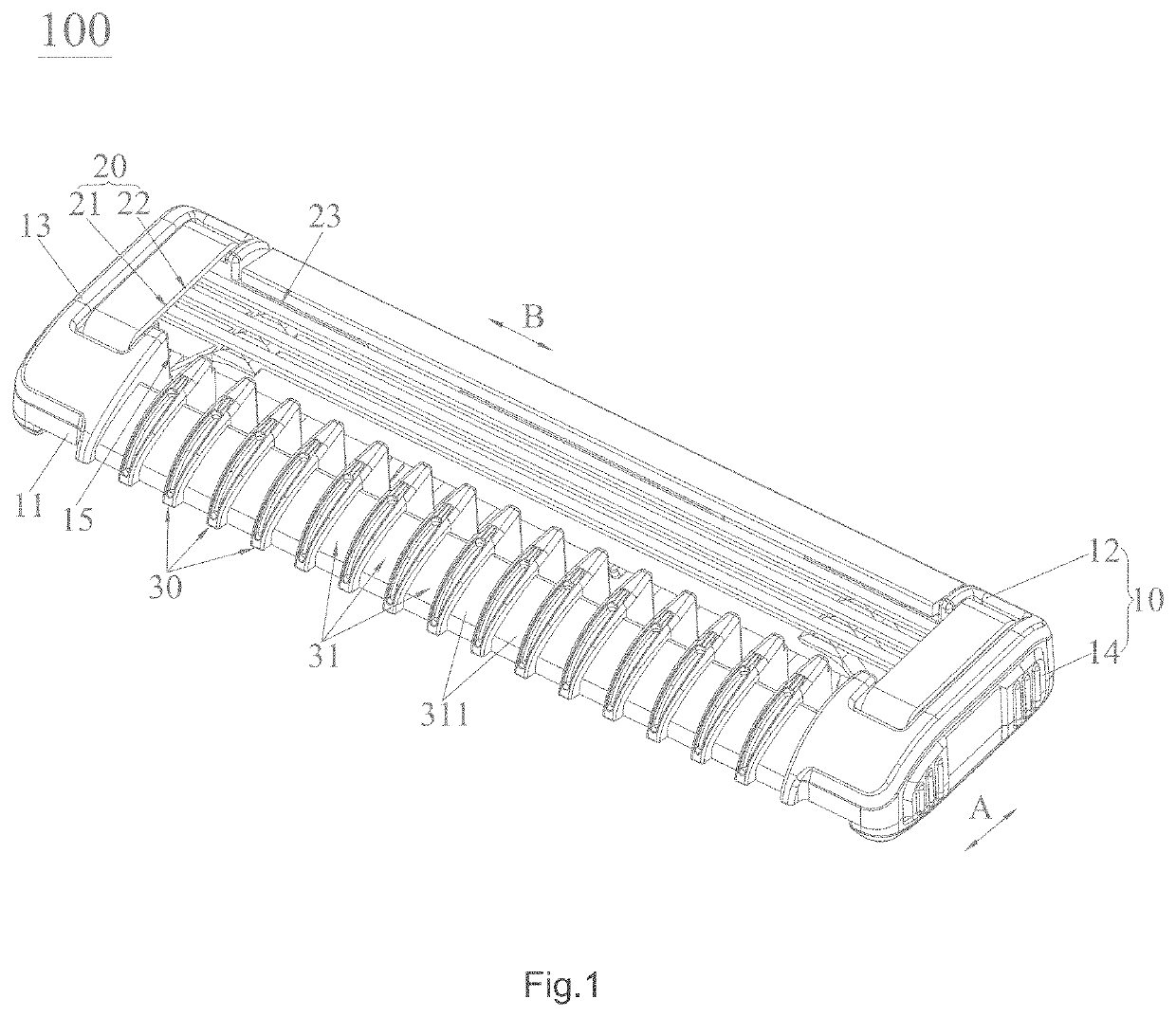
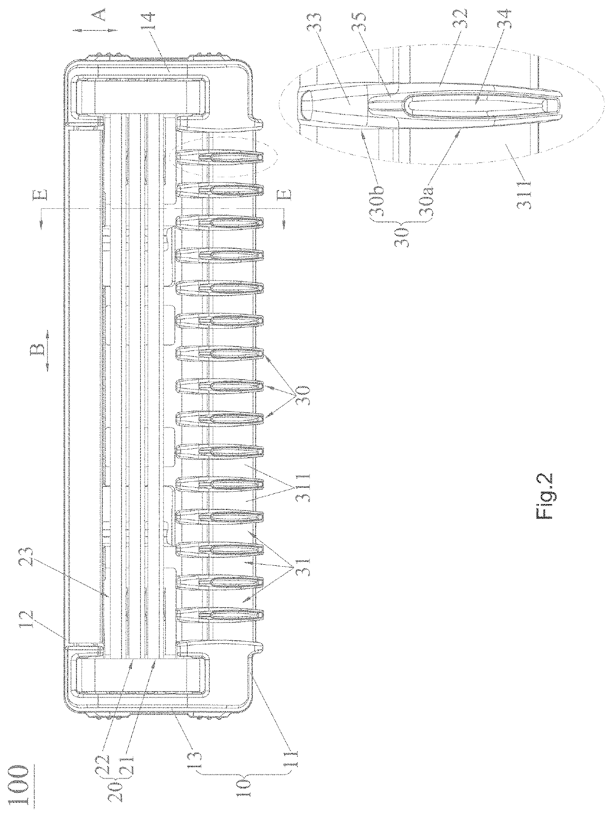
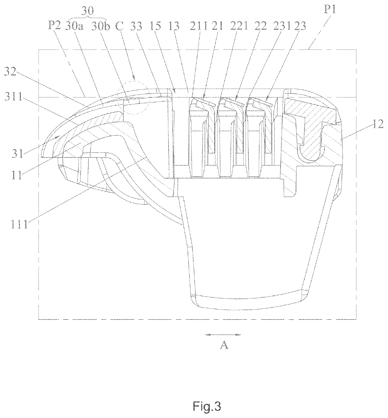
[0026]As shown in FIGS. 1-3 and 5, the razor head 100 includes a razor cartridge 10 and a razor blade 20. Specifically, the razor cartridge 10 includes a front side wall 11, a rear side wall 12, a left side wall 13 and a right side wall 14. Further, the front side wall 11 and the rear side wall 12 are separated along in a width direction of the razor cartridge 10, and the width direction of the razor cartridge 10 refers to a double arrow A. The left side wall 13 and the right side wall 14 are separated in a length direction of the razor cartridge 10, and the length direction of the razor cartridge 10 refers to a double arrow B. Specifically, the front side wall 11, the rear side wall 12, and the left side wall 13 and the right side wall 14 jointly enclose an accommodating space 15. Preferably, the front side wall 11, the rear side wall 12, ...


PUM


Abstract

Razor head includes a razor cartridge (10) and a razor blade (20). The razor cartridge (10) contains a front side wall (11), a rear side wall (12), a left side wall (13), and a right side wall (14) which enclose an accommodating space (15) to receiving the razor blade (20). The front side wall (11) has multiple protective ribs (30) protruding upward and arranged at intervals along the length direction of the razor cartridge (10); each protective rib (30) extends along the width direction of the razor cartridge (10) and contains a flexible protective rib (30a) and a rigid protective rib which (30b) which are joined, the rigid protective rib (30b) is located in front of the razor blade (20) and arranged adjacent to the razor blade (20), and a guide groove (31) is enclosed between the two adjacent protective rib (30). The razor head has good shaving performance and good comfort.

Description

FIELD OF THE INVENTION[0001]The present invention relates to the technical field of shaving, and more particularly to a razor head.BACKGROUND OF THE INVENTION[0002]With improvement of the economy and the society, abounding consumables are offered to people to satisfy people's demand, thereby improving people's standard or living. Razors are one of these consumables.[0003]Currently, razor head for a razor mainly includes a razor cartridge, blades, and a skin contact member. The razor cartridge includes a front side wall, a rear side wall, a left side wall, a right side wall, and a receiving space enclosed by the four side walls. The blades are located in the receiving space, left ends of the blades are assembled on the left side wall, and right ends of the blades are assembled on the right side wall. The skin contact member is located in front of the blades and assembled on the front side wall. The skin contact member has a plurality of convex strips arranged at intervals along a fro...

Claims


Application Information

Patent Timeline
Patent Type & Authority Patents(United States)
IPC IPC(8): B26B21/14
CPCB26B21/14B26B21/4018
Inventor REN, CHIJIN, YANQIUREN, XIANGRONG
Owner WENZHOU MERS R&D LTD
Learn More