Check patentability & draft patents in minutes with Patsnap Eureka AI!

Whipstock assembly for forming a window

a technology for forming windows and whipstocks, which is applied in the direction of sealing/packing, drilling machines and methods, and well accessories, etc., can solve the problems of reducing the durability of whipstocks during milling operations and the ability of whipstocks to deflect mill bits

Active Publication Date: 2022-09-06
WEATHERFORD TECH HLDG LLC
View PDF56 Cites 0 Cited by
  • Summary
  • Abstract
  • Description
  • Claims
  • Application Information

AI Technical Summary

Benefits of technology

The solution enables effective window formation and subsequent re-establishment of fluid communication while maintaining the structural integrity of the inner body for guiding tools, enhancing operational efficiency and durability.

Problems solved by technology

While such a metal composition aids in perforation of the whipstock, it also reduces the durability of the whipstock during the milling operation and the ability of the whipstock to deflect the mill bits against the casing.

Method used


Image

  • Whipstock assembly for forming a window
  • Whipstock assembly for forming a window
  • Whipstock assembly for forming a window

Examples


Embodiment Construction

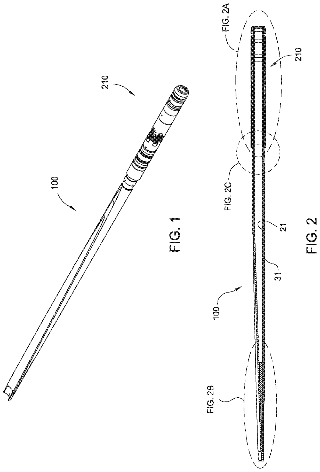
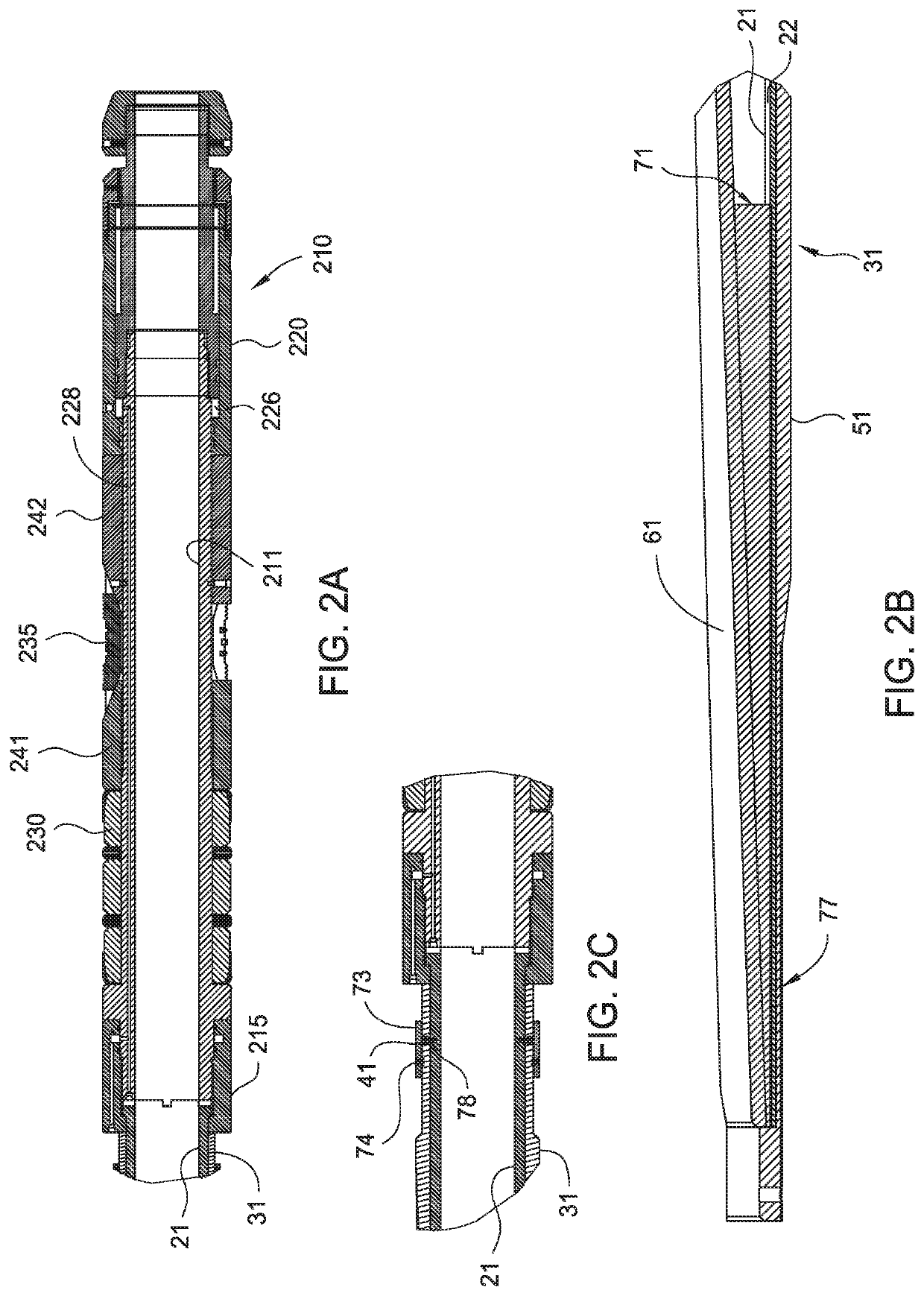
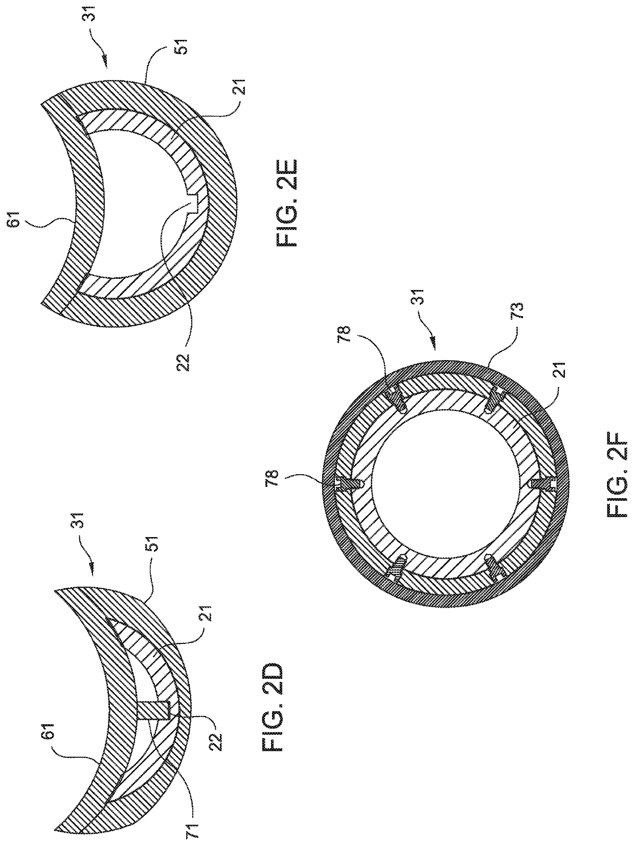
[0038]FIG. 1 is a perspective view of one embodiment of the whipstock assembly 100 for milling a window in a wellbore. FIG. 2 is a cross-sectional view of the whipstock 100 of FIG. 1. FIGS. 2A, 2B, and 2C are enlarged partial views of the whipstock 100 of FIG. 2. FIGS. 2D, 2E, and 2F are cross-sectional views of different sections of the whipstock 100 of FIG. 2. The whipstock 100 is shown attached to a packer and anchor assembly 210.

[0039]The whipstock 100 has a lower end for connecting to the packer and anchor assembly 210 and a concave shaped upper portion for guiding a drilling member such as a mill bit or a drill bit. In one embodiment, the whipstock 100 includes an outer sleeve body 31 disposed around an inner hollow body 21. As shown in FIG. 2C, the lower end of the outer body 31 is releasably attached to the inner body 21 using a shearable member 41 such as a shear screw. The lower end of the inner body 21 is coupled to the packer and anchor assembly 210 and configured to tra...


PUM


Abstract

A whipstock assembly includes an inner body having a bore and an inclined surface at an upper portion; and an outer body disposed around the inner body and releasably attached to the inner body, the outer body having an inclined surface and an upper portion closed to fluid communication.

Description

BACKGROUNDField[0001]Embodiments of the present disclosure relate to sidetrack drilling for hydrocarbons. In particular, this disclosure relates to a whipstock assembly for creating a window within a wellbore casing. More particularly still, this disclosure relates to a whipstock assembly having a removable sleeve for re-establishing fluid communication with wellbore.Description of the Related Art[0002]In recent years, technology has been developed which allows an operator to drill a primary vertical well, and then continue drilling an angled lateral borehole off of that vertical well at a chosen depth. Generally, the vertical, or “parent” wellbore is first drilled and then supported with strings of casing. The strings of casing are cemented into the formation by the extrusion of cement into the annular regions between the strings of casing and the surrounding formation. The combination of cement and casing strengthens the wellbore and facilitates the isolation of certain areas of t...

Claims


Application Information

Patent Timeline
Patent Type & Authority Patents(United States)
IPC IPC(8): E21B29/06E21B33/12E21B23/01
CPCE21B29/06E21B23/01E21B33/12E21B7/061
Inventor TAYLOR, JR., JAMES H.
Owner WEATHERFORD TECH HLDG LLC
Features
  • R&D
  • Intellectual Property
  • Life Sciences
  • Materials
  • Tech Scout
  • Unparalleled Data Quality
  • Higher Quality Content
  • 60% Fewer Hallucinations
Learn More