Water wand

Inactive Publication Date: 2001-11-22
SHRIGLEY ROSS P
View PDF0 Cites 39 Cited by
  • Summary
  • Abstract
  • Description
  • Claims
  • Application Information

AI Technical Summary

Benefits of technology

0006] In accordance with the present invention there is provided a unique water wand which can be attached to the end of a flexible hose and is useful for dispensing a very uniform and gentle pattern of water or other fluid. The hand-held wand comprises an elongated tubular body having an open end and a closed end (preferabl

Problems solved by technology

A common problem with watering a flat of flowers or a flower bed is that it is difficult to know how much watering has been done on it without probing through the soil in several areas.
Current shower head or circular hole pattern

Method used


Image

  • Water wand
  • Water wand
  • Water wand

Examples


Embodiment Construction

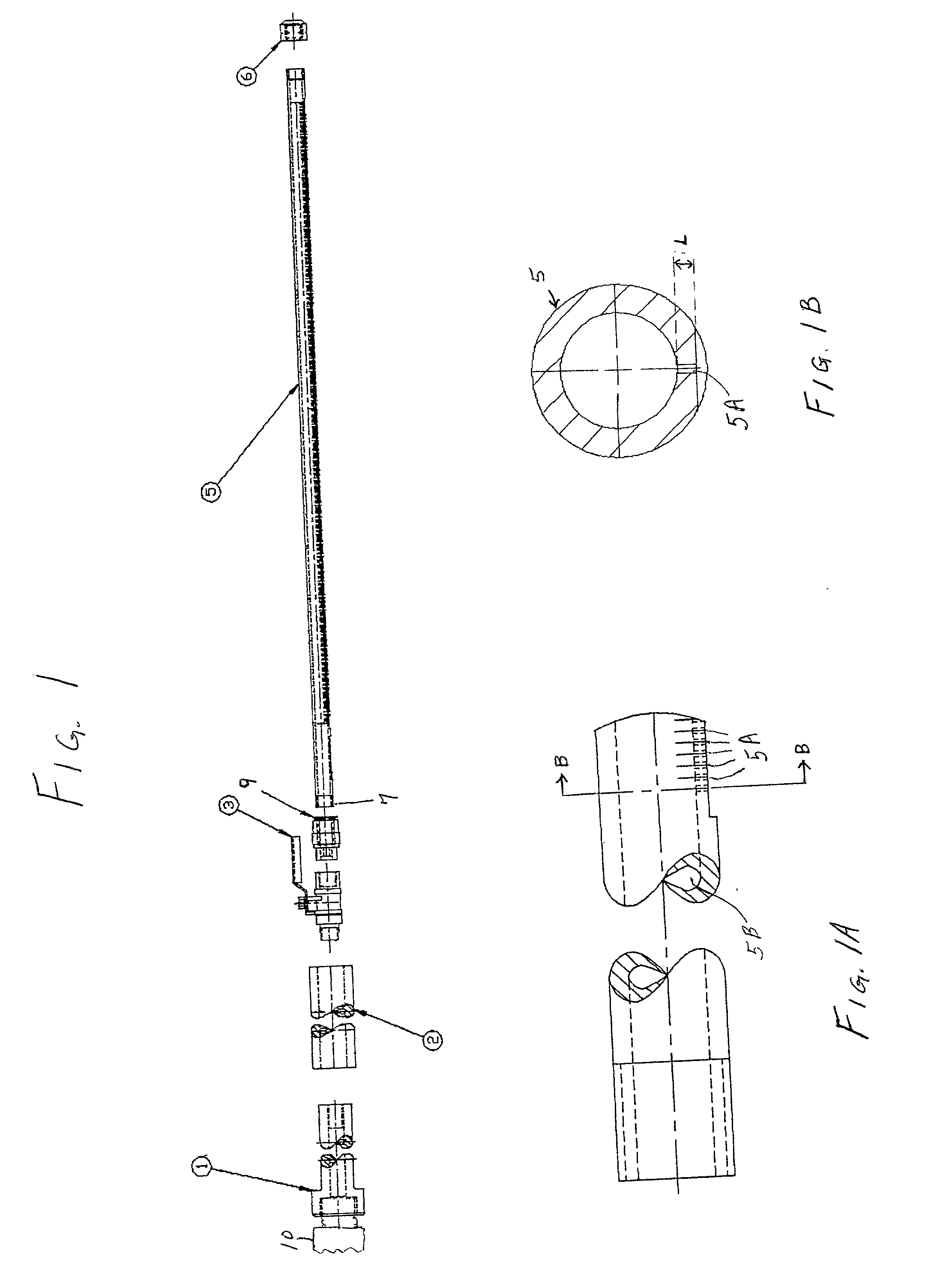
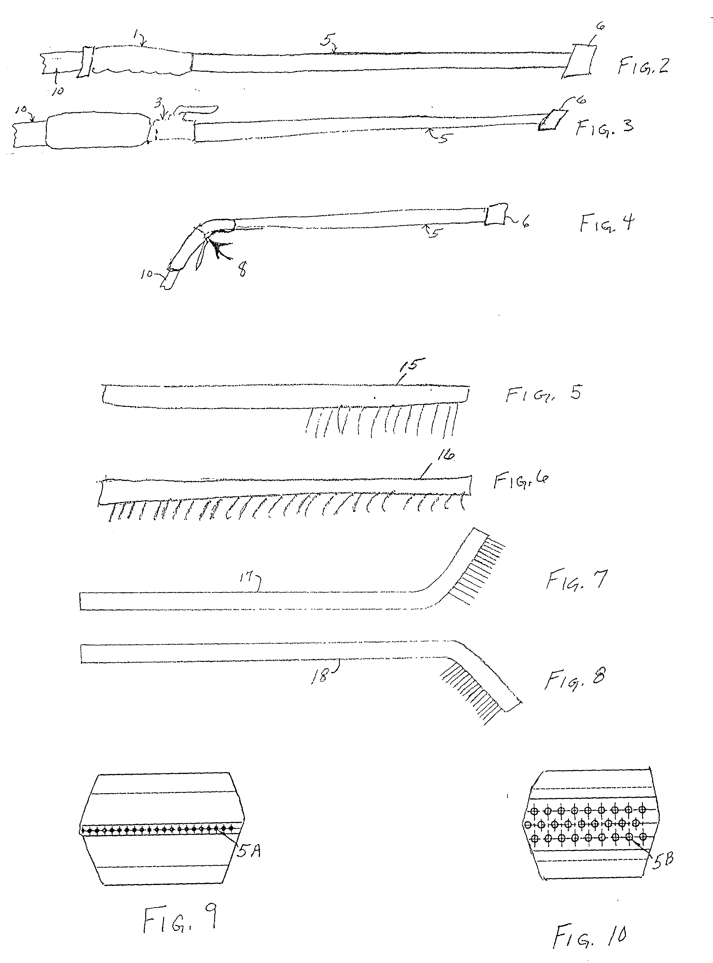
[0023] In FIGS. 1 and 1A there is shown one embodiment of a watering wand which includes an elongated tubular body 5 having an open end 7 and an opposite end which is closed by means of removable cap 6. The tubular body includes a plurality of openings 5A extending through a side wall of the tubular body so as to communicate with the interior passageway 5B of the tubular body. By having the removable cap 6 on the outer end of the wand, general maintenance of the wand is greatly facilitated. Dirt and debris can get into hoses which can clog the holes of the wand. By simply removing the cap 6, any dirt or debris can be flushed out through the outer end of the wand. When holes are clogged in any watering apparatus, water is deflected, and this results in a disruption of any intended accuracy or attempt at even coverage. Also, any debris caught in the holes can be simply pushed through and into the interior of the wand where it can be flushed out the end. The device of this invention th...


PUM


Abstract

A hand-held, portable dispensing device (i.e. a wand) is described for dispensing a curtain spray pattern of liquid which includes an elongated tubular body having an open end and a closed end. The open end can be connected to a flexible hose or the like for supplying pressurized liquid to the tubular body which has a plurality of spaced openings along its length on one side. The spacing of the discharge openings is determined by the diameter of the openings, and the ratio of the total area of the openings to the inside diameter of the tubular body is in a defined range. The openings can be in a single line or in a plurality of rows, for example, An adjustable control valve and a quick connect coupler can also be included.

Description

CROSS-REFERENCE TO RELATED APPLICATIONS[0001] This application is a continuation-in-part of my earlier application Ser. No. 09 / 465,051, filed Dec. 16, 1999, which claimed the benefit of my Provisional Application No. 60 / 114,560, filed Dec. 31, 1998.FIELD OF THE INVENTION[0002] This invention relates to fluid dispensing devices. More particularly, this invention relates to devices for dispensing liquids such as water, etc.BACKGROUND OF THE INVENTION[0003] A variety of devices has been used for dispensing pressurized fluids such as water from a flexible hose. For example, a spray nozzle is commonly attached to the end of the hose. Spray nozzles typically include a pistol grip and a movable trigger which controls the flow rate of water through the nozzle. The nozzle style and design determine the spray pattern of water exiting the nozzle. See, for example, U.S. Pat. No. 5,598,978. Spray wands have also been described, e.g. in U.S. Pat. Nos. 4,982,896 and 5,419,496. Another type of plan...

Claims


Application Information

Patent Timeline
IPC IPC(8): B05B1/16B05B1/20
CPCB05B1/1645B05B1/20
Inventor SHRIGLEY, ROSS P.
Owner SHRIGLEY ROSS P
Why Eureka
Try Eureka