Bar code scanner with collimated scan volume

a bar code scanner and scanning volume technology, applied in the field of automatic bar code symbol reading system, can solve the problems of difficult manipulation inconvenient assembly-line applications, and inconvenient use of hand-held laser scanners, so as to facilitate rapid steady-state response, conserve battery power consumption, and save power consumption

Inactive Publication Date: 2001-11-29
SCHMIDT MARK C +3
View PDF0 Cites 15 Cited by
  • Summary
  • Abstract
  • Description
  • Claims
  • Application Information

AI Technical Summary

Benefits of technology

[0015] It is another object of the present invention to provide such an automatic bar code symbol reading system, wherein a highly collimated laser scanning pattern is projected from the hand-supportable device about a projection axis, and comprises laser scanning planes which intersect within a narrowly confined scanning volume extending about the projection axis so that bar code symbols disposed within the scanning volume can be read omnidirectionally, while inadvertent scanning of bar code symbols outside of the scanning volume is prevented.
[0051] FIG. 1C is an elevated side view of the illustrative embodiment of the automatic bar code symbol reading device hereof, illustrating that the mass balance of the hand-supportable bar code symbol reading device has been designed to minimize torques about the point of pivot of the housing which occurs about the user's index finger in order to maximize its ergonomic handling efficiency eliminate fatigue during automatic hands-on, omnidirectional laser scanning operations;

Problems solved by technology

While prior art hand-held and stationary laser scanners have played an important role in the development of the bar code symbol industry, these devices have, however, suffered from a number of shortcomings and drawbacks.
For example, hand-held laser scanners, although portable and lightweight, are not always convenient to use in assembly-line applications where the user processes bar coded objects over an extended period of time, or where the user requires the use of both hands in order to manipulate the objects.
In some applications, hand-held laser scanners are difficult to manipulate while simultaneously moving objects or performing other tasks at a point-of-sale terminal.
However, by their nature, stationary laser scanners render scanning large, heavy objects a difficult task as such objects must be manually moved into or through the laser scan field.
While the bar code symbol scanning system of U.S. Pat. No. 4,776,297 permits reading of printed bar code information using either a portable "hands-on" or stationary "hands-free" mode of operation, this system suffers from several significant shortcomings and drawbacks as well.
However, in many instances where both hands are required to manipulate a bar coded object, the object is too large to be passed between the head and base portions of the fixture and thus scanning of the bar code symbol is not possible.
While each of these systems produces an omnidirectional laser scan pattern from a hand-supportable housing and have hands-free and hands-on modes of operation, each of these scanning devices suffer from a number of shortcomings and drawbacks.
In particular, the spatial extent of the laser scan pattern produced from each of these scanners frequently results in the inadvertent scanning of code symbols on products placed near the scanner during its hands-free mode of operation.
In the hands-on mode of operation, it is virtually impossible to use the scanners to read bar code symbol menus provided in diverse application environments.
Moreover, in each of these scanner designs, the scanner is tethered to its base unit by a power / signal cord, and the user is required to handle the scanner housing in an awkward manner in the hands-on mode of operation, resulting in strain and fatigue and thus a decrease in productivity.
In addition, the control structure provided in each of these hand-held projection scanners operates the scanner components in a manner which involves inefficient consumption of electrical power, and prevents diverse modes of automatic code symbol reading which would be desired in portable scanning environments.

Method used


Image

  • Bar code scanner with collimated scan volume
  • Bar code scanner with collimated scan volume
  • Bar code scanner with collimated scan volume

Examples


Embodiment Construction

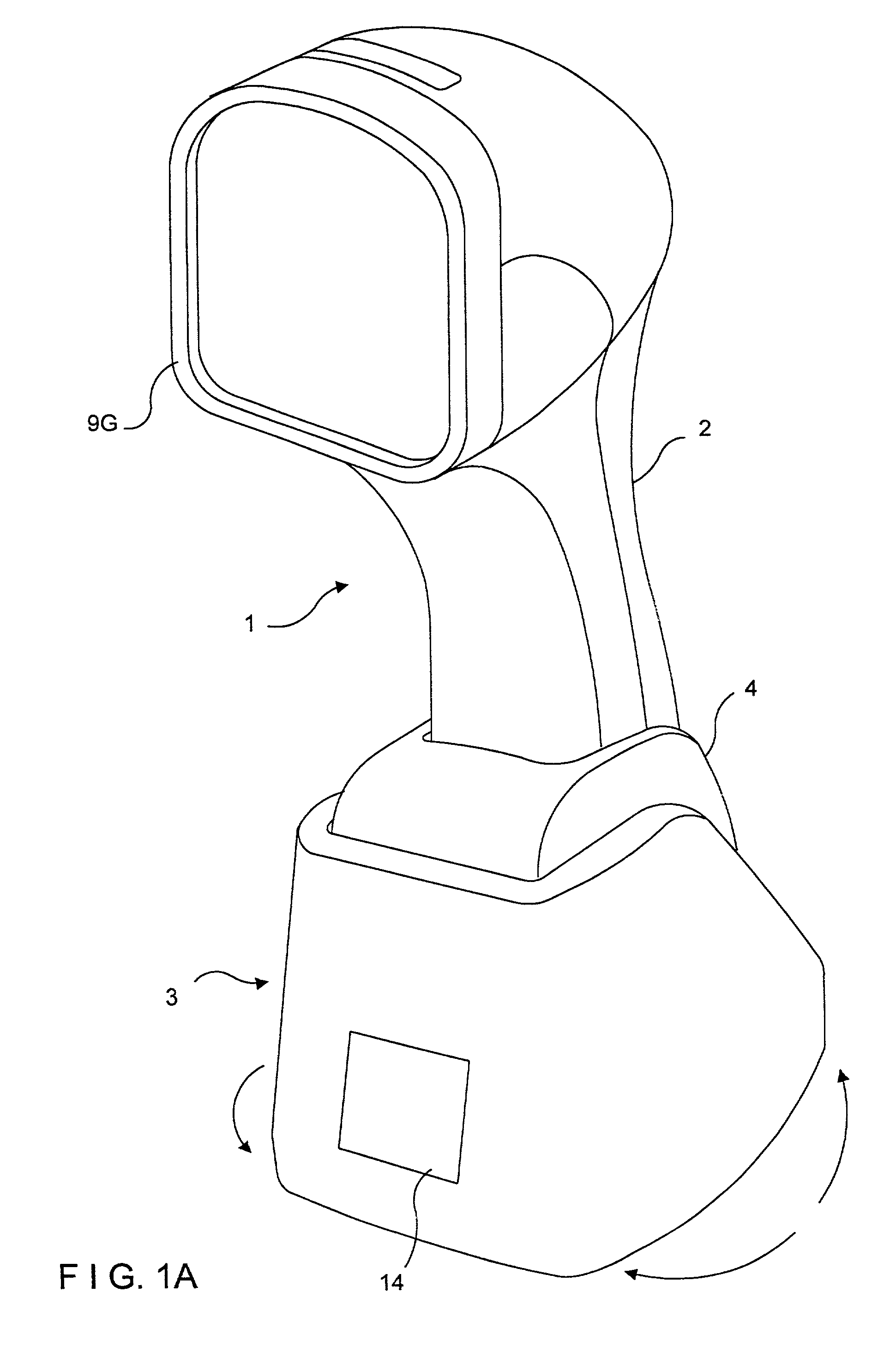
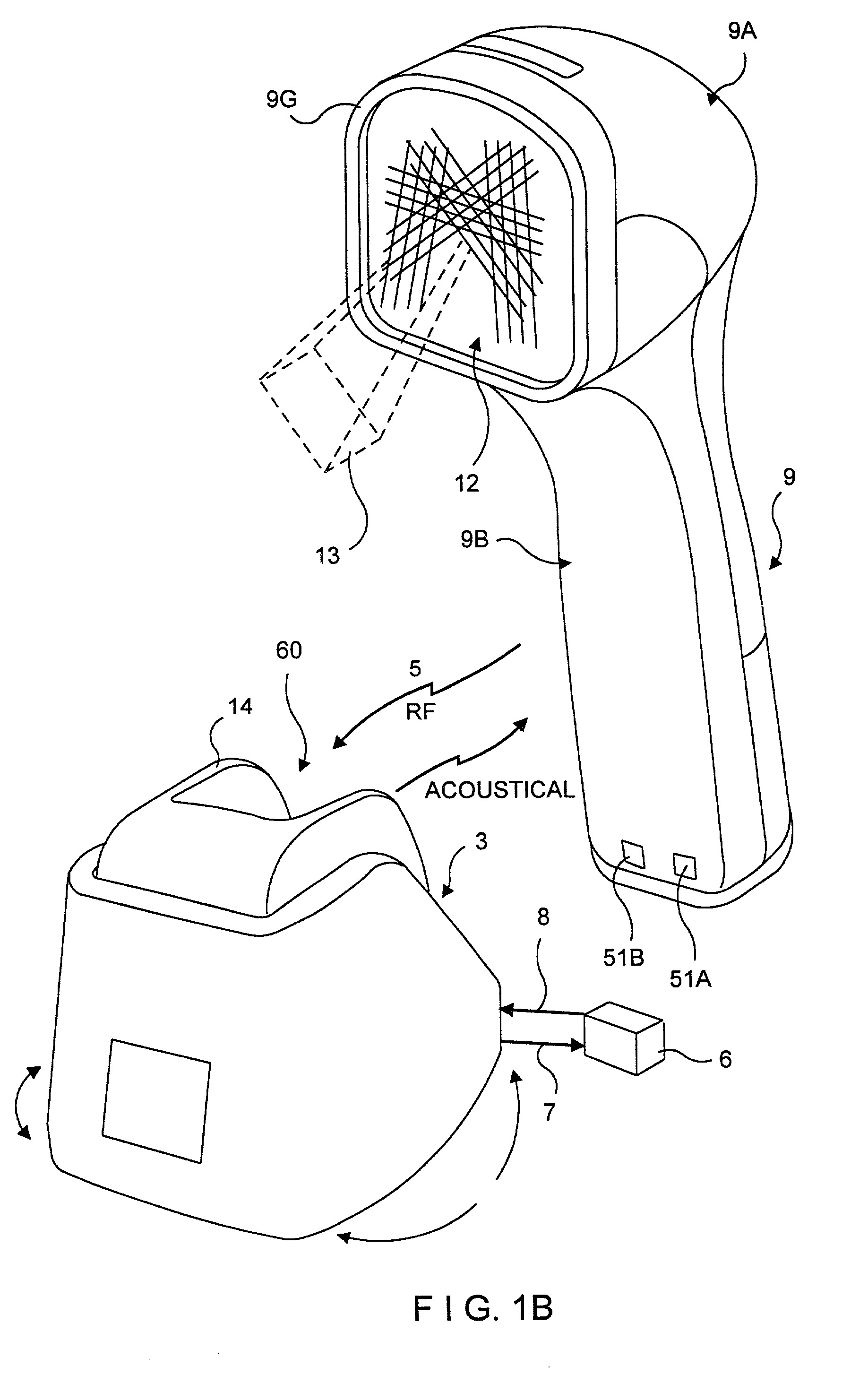
[0097] As shown in FIGS. 1 to 3B, automatic bar code symbol reading system 1 of the illustrative embodiment of the present invention comprises an automatic (i.e., triggerless) portable bar code (symbol) reading device 2 operably associated with a base unit 3 having a scanner support stand 4 pivotally connected thereto, for releasably supporting the automatic bar code symbol reading device 2 at any one of a number of positions above of a counter surface at a Point of Sale (POS) station. In the preferred embodiment, the bar code symbol reading device 2 is operably connected with its the base unit 3 by way of a one way electromagnetic link 5 that is momentarily created between bar code symbol reading device 2 and its mated base unit 3 after the successful reading of each bar code symbol by the bar code symbol reading device. Operable interconnection between the base unit and a host system (e.g., electronic cash register system, data collection device, etc.) 6 is achieved by a flexible ...


PUM

PropertyMeasurementUnit
obtuse angleaaaaaaaaaa
wavelengthsaaaaaaaaaa

Abstract

An optical scanner comprising an automatic (i.e., triggerless) portable bar code symbol reading device with an omnidirectional scanning engine mounted within the head portion of its housing, and adapted for use with an associated base unit. The bar code symbol reading device produces a confined scanning volume for omnidirectional scanning of code symbols presented therein, while preventing unintentional scanning of code symbols on nearby objects located outside of the confined scanning volume.

Description

[0001] 1. Field of the Invention[0002] The present invention relates generally to laser scanning systems, and more particularly to an automatic bar code symbol reading system in which an automatic hand-supportable laser scanner can be interchangeably utilized as either a portable hand-held laser scanner in an automatic "hands-on" mode of operation, or as a stationary laser projection scanner in an automatic "hands-free" mode of operation.[0003] 2. Brief Description of the Prior Art[0004] Bar code symbols have become widely used in many commercial environments such as, for example, point-of-sale (POS) stations in retail stores and supermarkets, inventory and document tracking, and diverse data control applications. To meet the growing demands of this recent technological innovation, bar code symbol readers of various types have been developed for scanning and decoding bar code symbol patterns and producing symbol character data for use as input in automated data processing systems.[0...

Claims


Application Information

Patent Timeline
Patent Type & Authority Applications(United States)
IPC IPC(8): A61K38/00A61K39/00C07K14/205G02B26/10G06K7/10G06K7/14G06K17/00G07G1/00
CPCA61K38/00A61K39/00C07K14/205G02B26/10G02B26/106G06K7/10G06K7/10564G06K7/10584G06K7/10594G06K7/10603G06K7/10663G06K7/10673G06K7/10693G06K7/10702G06K7/10792G06K7/10801G06K7/10811G06K7/10851G06K7/10861G06K7/10871G06K7/10881G06K7/10891G06K7/109G06K7/14G06K7/1443G06K17/0022G06K2207/1012G06K2207/1013G06K2207/1017G07F11/002G07G1/0045G07F9/002
Inventor SCHMIDT, MARK C.KNOWLES, CARL H.WILZ, DAVID M. SR.ROCKSTEIN, GEORGE B.
Owner SCHMIDT MARK C
Why Eureka
Try Eureka