Support device for a motorised flying instrument in a wind tunnel

a technology of supporting device and flying instrument, which is applied in the direction of machine supports, indication/recording movement, sport apparatus, etc., can solve the problems of inability to study the dynamic behaviour of an instrument with its motor on, long implementation time, and difficulty in real-time implementation of conventional technology

Inactive Publication Date: 2002-02-28
AEROSPATIALE MATRA MISSILES
View PDF1 Cites 6 Cited by
  • Summary
  • Abstract
  • Description
  • Claims
  • Application Information

AI Technical Summary

Problems solved by technology

On the other hand, such support devices cannot be used to study the behaviour of a flying instrument whose motor or motors are switched on.
Indeed, the presence of a boom approximately in the extension of the model, to its rear, does not allow a motor located in the longitudinal axis of the instrument to be switched on and greatly disturbs the airflow leaving a motor offset relativ

Method used


Image

  • Support device for a motorised flying instrument in a wind tunnel
  • Support device for a motorised flying instrument in a wind tunnel
  • Support device for a motorised flying instrument in a wind tunnel

Examples


Embodiment Construction

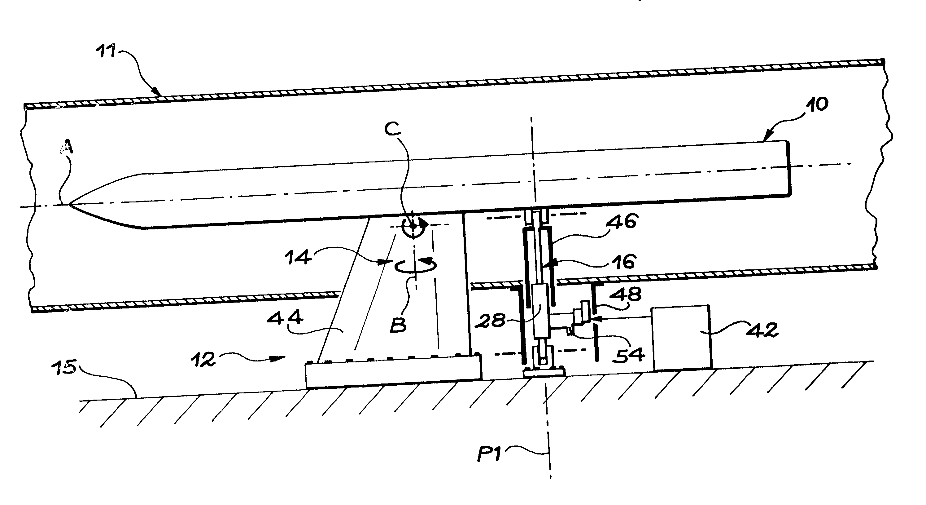
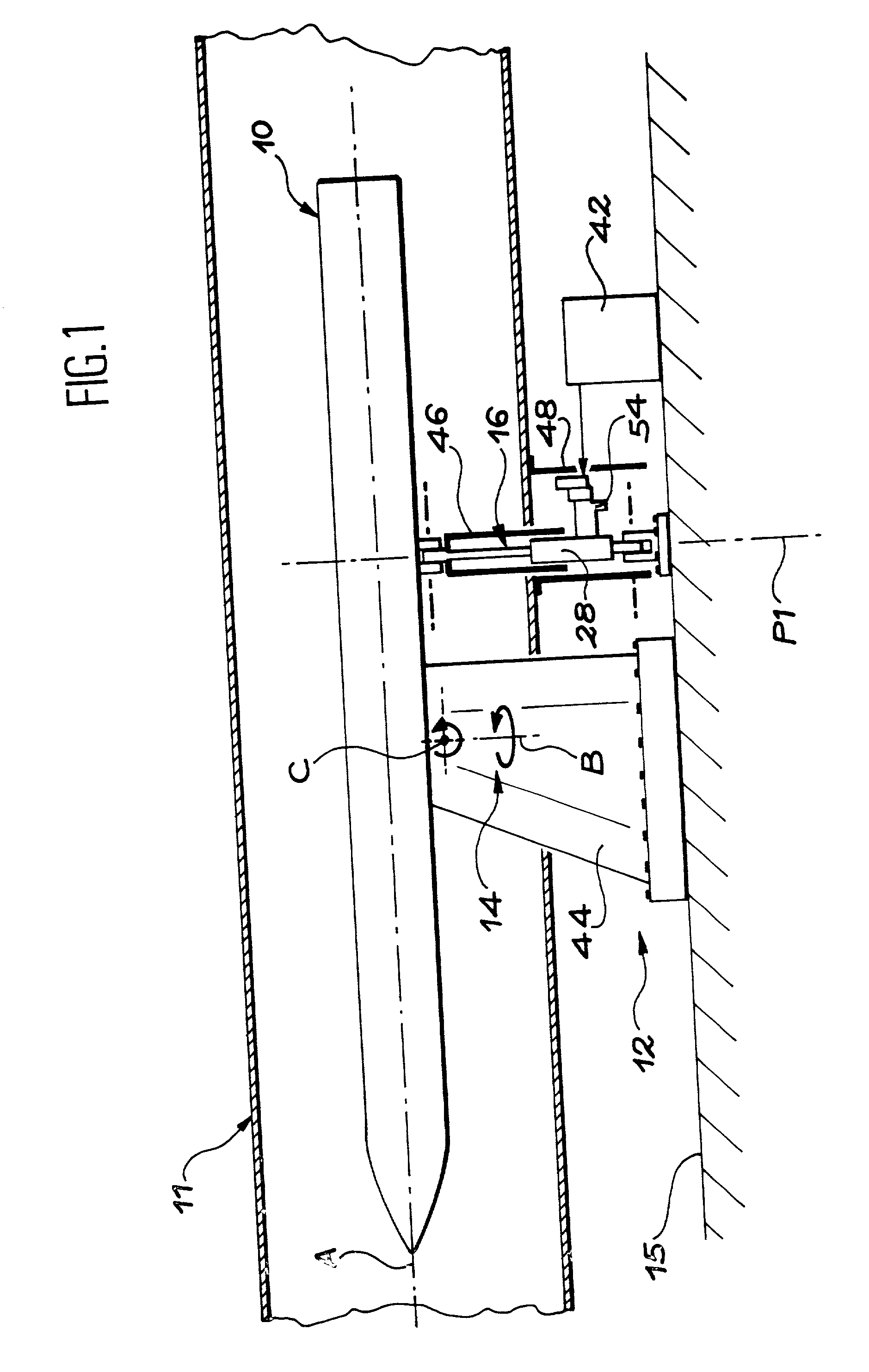
[0027] In FIGS. 1 and 2, a diagram is given showing a flying instrument 10 such as a prototype or a missile model, placed in a wind tunnel 11. The flying instrument 10 is fitted with one or more motors intended to be switched on when wind tunnel tests are carried out.

[0028] In accordance with the invention, the flying instrument 10 is connected to the fixed structure of the wind tunnel by a support device 12 designed to simulate, in real time and hands off, changes in dynamics of the instrument 10, representative of the its flight attitudes when it passes through a given trajectory or trajectory fraction.

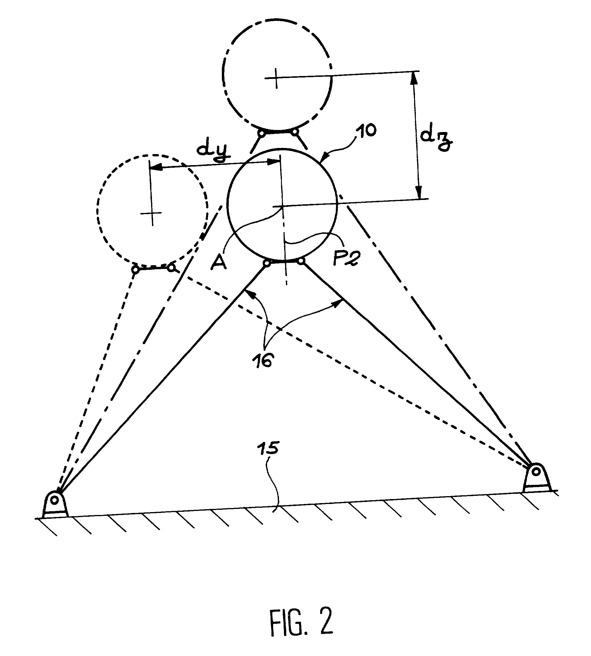
[0029] In the preferred embodiment of the invention shown in the figures, the support device 12 includes a front support 14 and two rear supports 16.

[0030] In this case, the front support 14, of invariable length, connects the instrument 10 to the floor 15 of the fixed structure of the wind tunnel 11. It is located in a vertical plane passing through the longitudinal axis A of the i...


PUM


Abstract

A support device for a motorized flying instrument in a wind tunnel. To carry out tests in a wind tunnel on a motorized flying instrument (10), with the motor on, under different attitudes hands off, the instrument is connected to the fixed structure (15) of the wind tunnel (11) by a mounting device (12) at least one of the supports (14, 16) of which is fitted with a length adjustment system, such as a hydraulic jack (28). This jack (28) is remote controlled, in real time, by a control system (42).

Description

[0001] The invention relates to a device designed to support a flying instrument such as a prototype or a missile model in a wind tunnel, so as to study the behaviour of this instrument under different attitudes, with its motor on.[0002] The invention applies to wind tunnel tests carried out on any type of motorised flying instrument and particularly a prototype or a scale one model, fitted with a motor, of a missile of which it is desired to study the behaviour in real time in a supersonic tunnel, hands off, by reconstructing the changes in dynamics representative of the flight attitudes of the instrument.PRIOR ART[0003] As shown in documents FR-A-2 159 548 and FR-A-2 641 378, there is a known technique of wind tunnel testing the aerodynamic behaviour of a model of a flying instrument such as an aeroplane by mounting this model on a boom connected to the fixed structure of the wind tunnel by a set of mechanisms allowing the attitude of the model being tested to be varied in real ti...

Claims


Application Information

Patent Timeline
IPC IPC(8): F42B15/00F02K9/96F16M1/00G01M9/04G01M9/06
CPCG01M9/04
Inventor DEMAY, JEAN-PAULCARTON, LAURENT
Owner AEROSPATIALE MATRA MISSILES
Why Eureka
Try Eureka